Gumball Lamp Board History
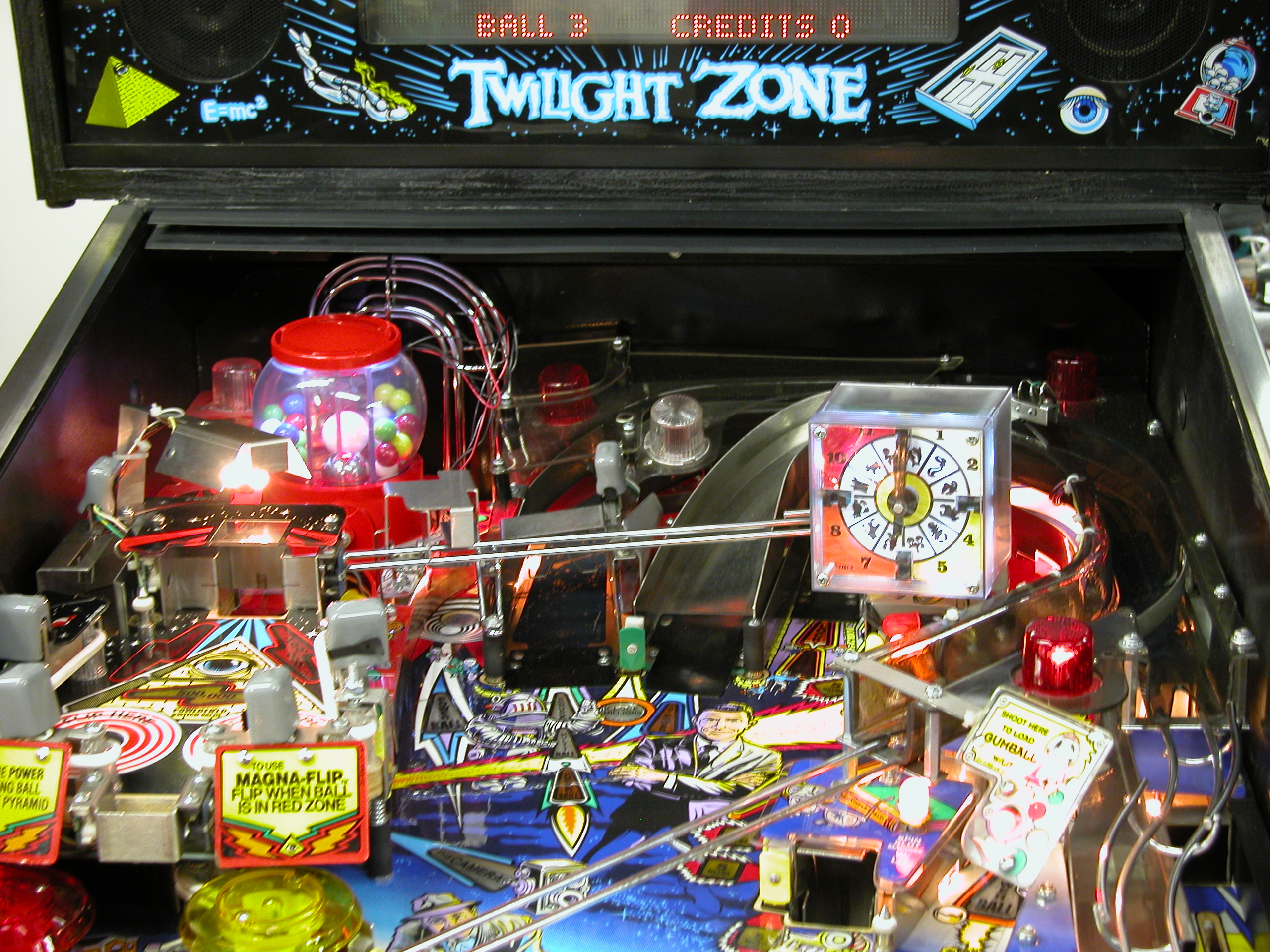
So I want to dress up my gumball machine. It's a bit dark up there. Obviously, we start with gumballs. I got some really nice glass ones from Terry at Pinball Life; I also have some steel ones that will match the backglass a little better. Common sense tells me that it isn't good to put little missiles in the gumball, but I think that it could do with some visual improvement. Once I have done that. I will need some light to see them. So I have designed a lighting board, and have to decide what colors to use. The board will light the side compartments all the time with two LEDs each, and flash (probably rather brightly, given that I have 6 LEDS in there) the main compartment. I think that white is the best choice for the outsides; inside, white or maybe blue. I have some warm white LEDs coming, we'll see what they look like. I tried UV on my gumballs, no luck.
The gumball lamp board schematic and layout are down at the bottom of this page. It has four LEDs for the GI 6.3V circuit, and 6 LEDs for the 12V circuit. For R1 and R3, 47 ohm resistors will be about right for 20mA rated white LEDs. For the 12V circuit, the resistors will have to be 150 ohms for white or blue LEDs at 20mA.The schematic shows 100 ohms, but I suspect that this might be a bit bright with 6 LEDs in the string! For red LEDs, 470 ohms will be about right.
I bought a bulk lot of 5000mcd white LEDs from eBay, and they work well in this application.
The actual board is 1.8 by 1.1 inches, and will fit inside the gumball machine cap if the gumball divider is notched.
Update December 23, 2004
My boards arrived today. Not bad, considering that I ordered them on Monday at midnight! Definitely one up for Advanced Circuits. Price wasn't bad either - $66 for 5 boards, which I had to cut into halves. My next round will probably go to Olimex, though - half the price and I get silkscreen and solder mask. They are made in Bulgaria, though, so it will take about 3 weeks to get here.
Assembling the first board took about 15 minutes, and it worked right off. I built it with 5000 mcd white LEDS. At first, I was worried about too much light but in fact I might like it a little brighter.
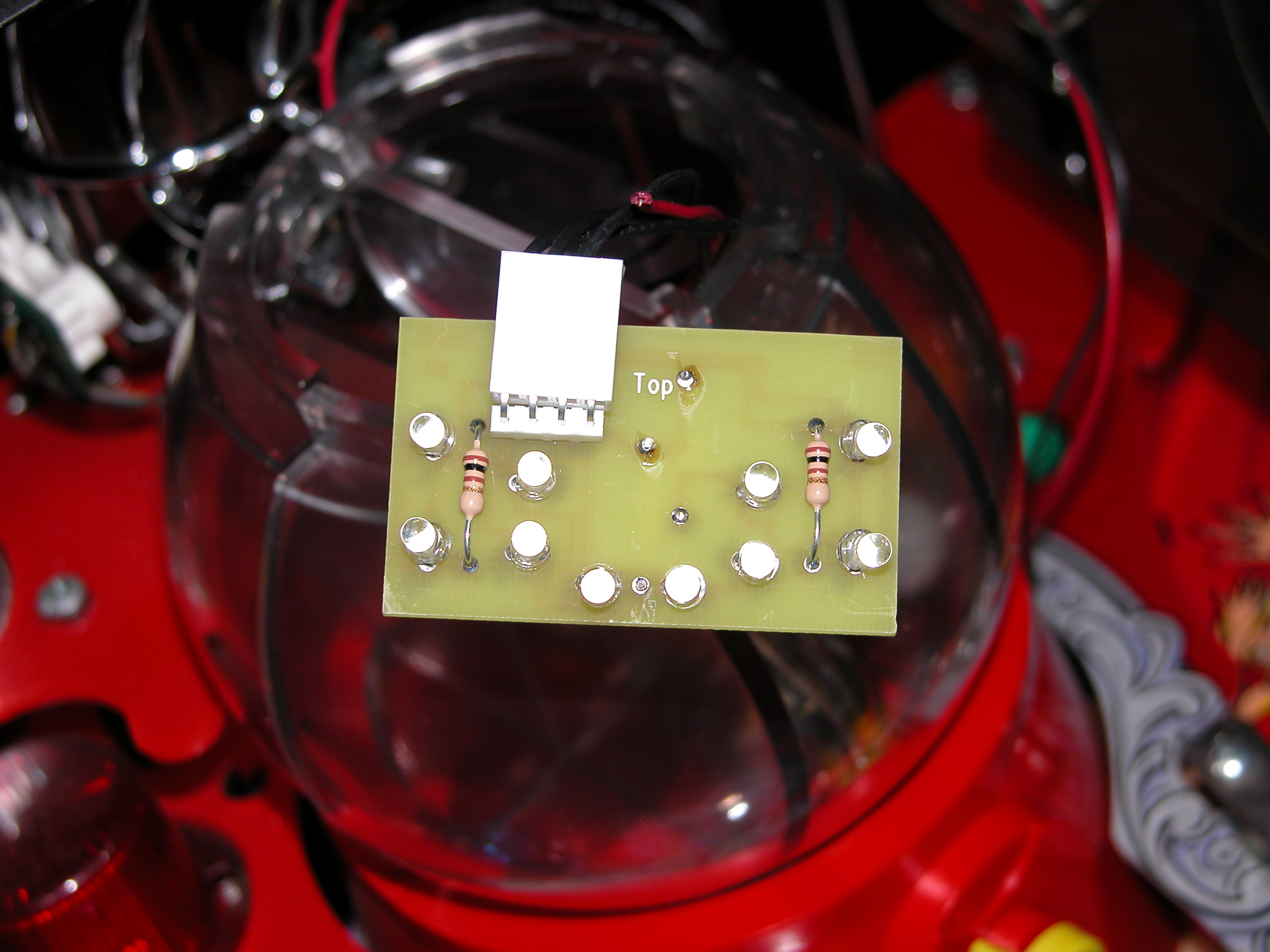
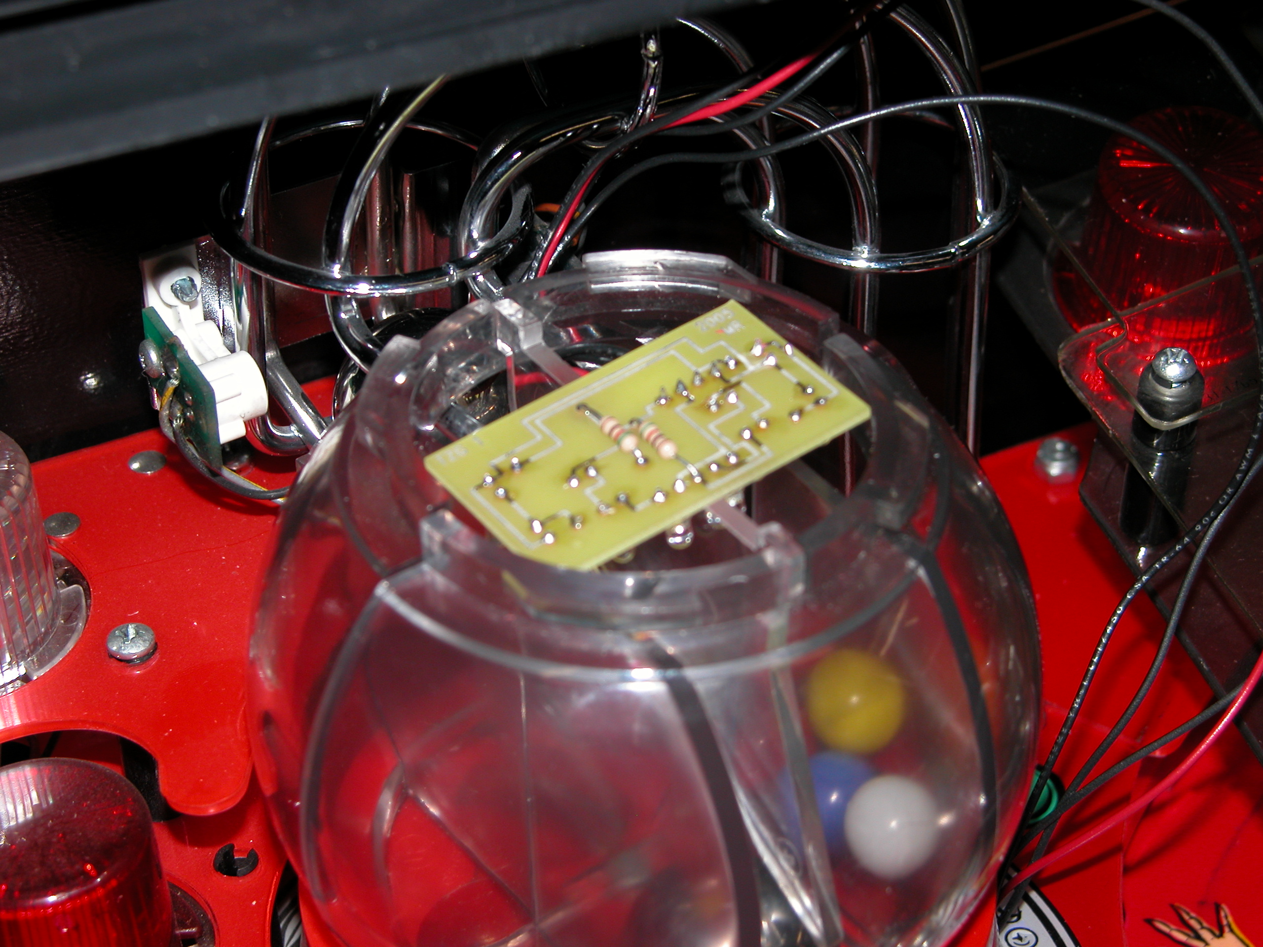
Here's the board from the top, and inserted into the gumball. Now, some pictures in action:
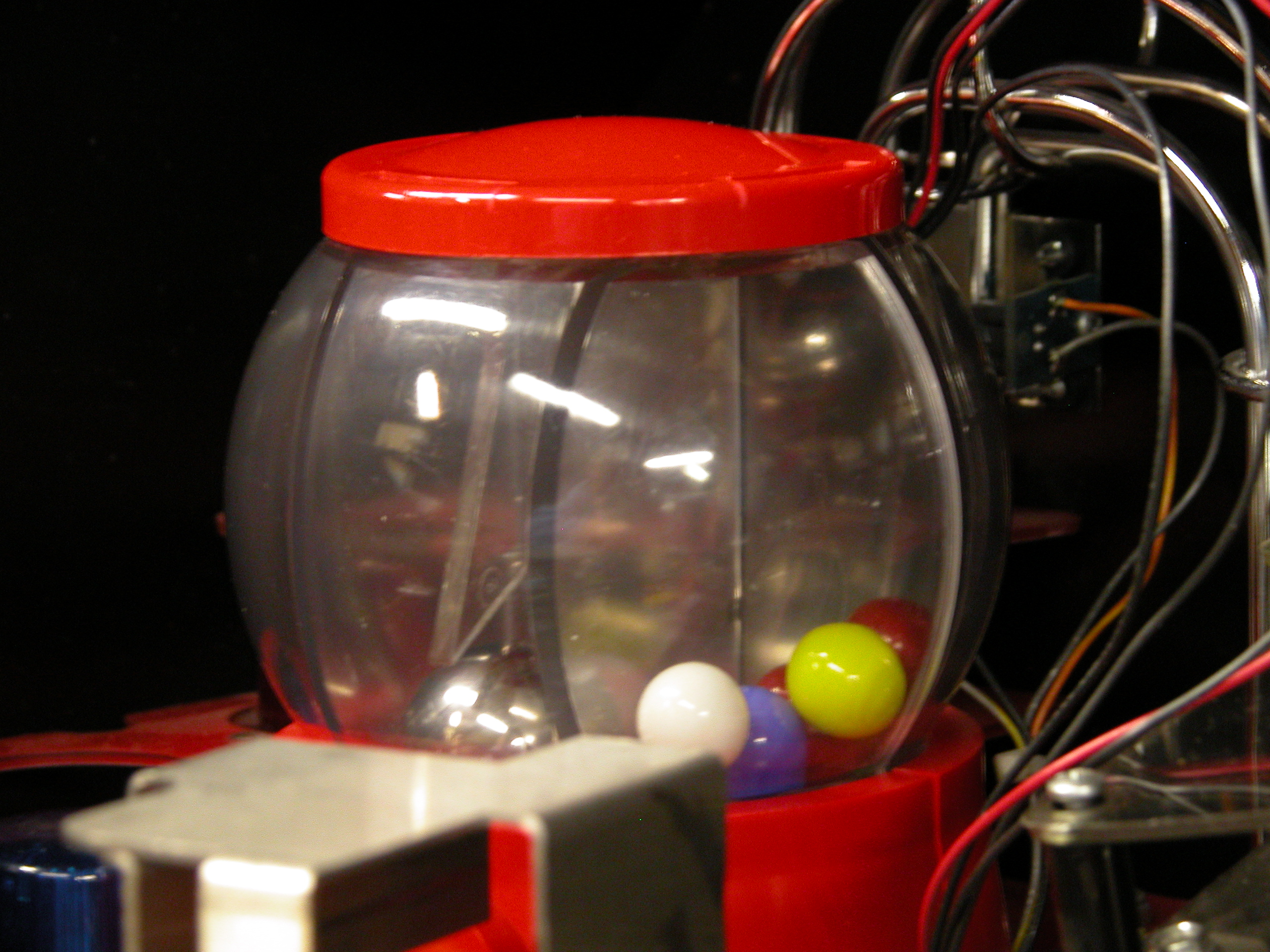
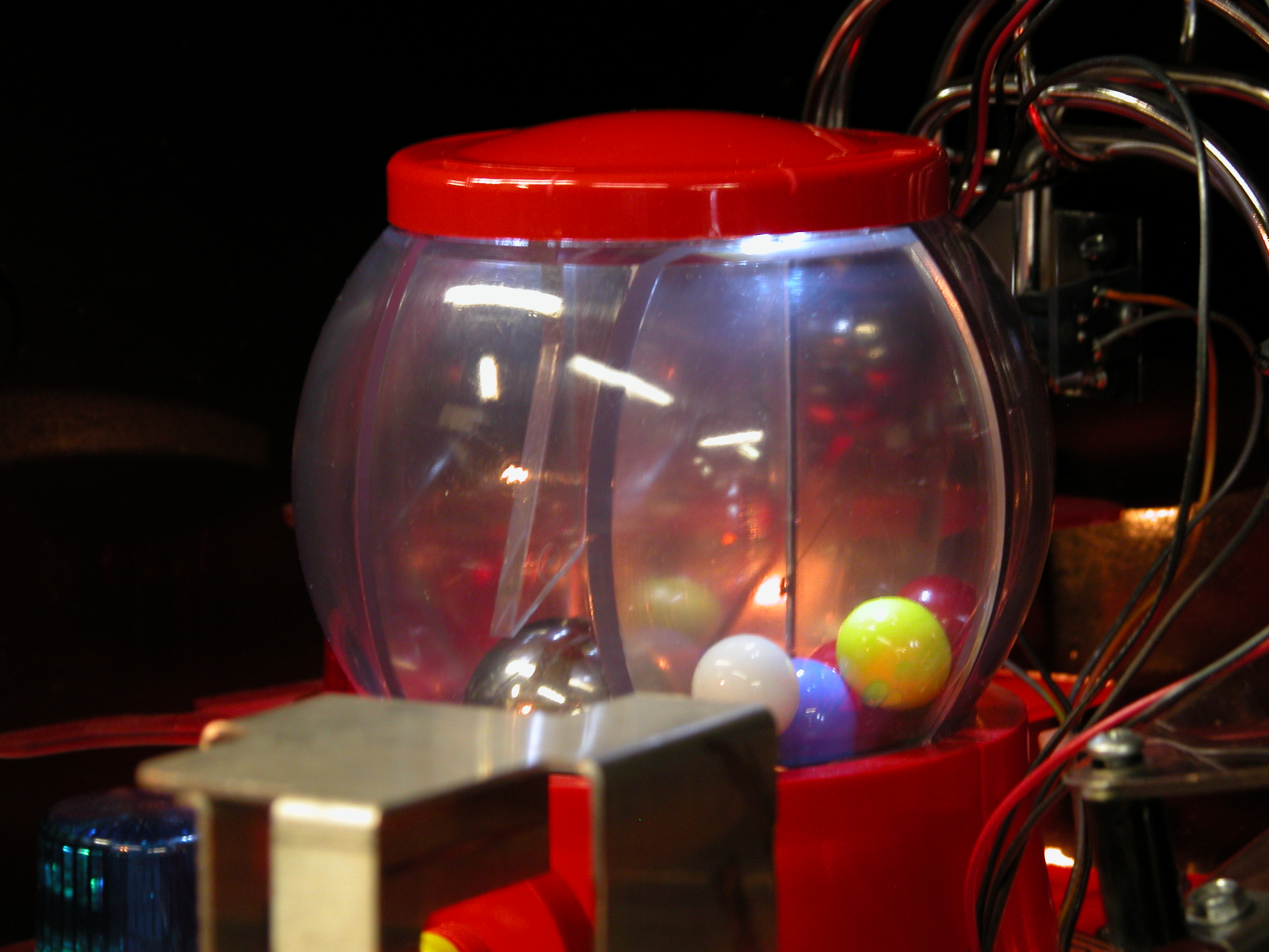
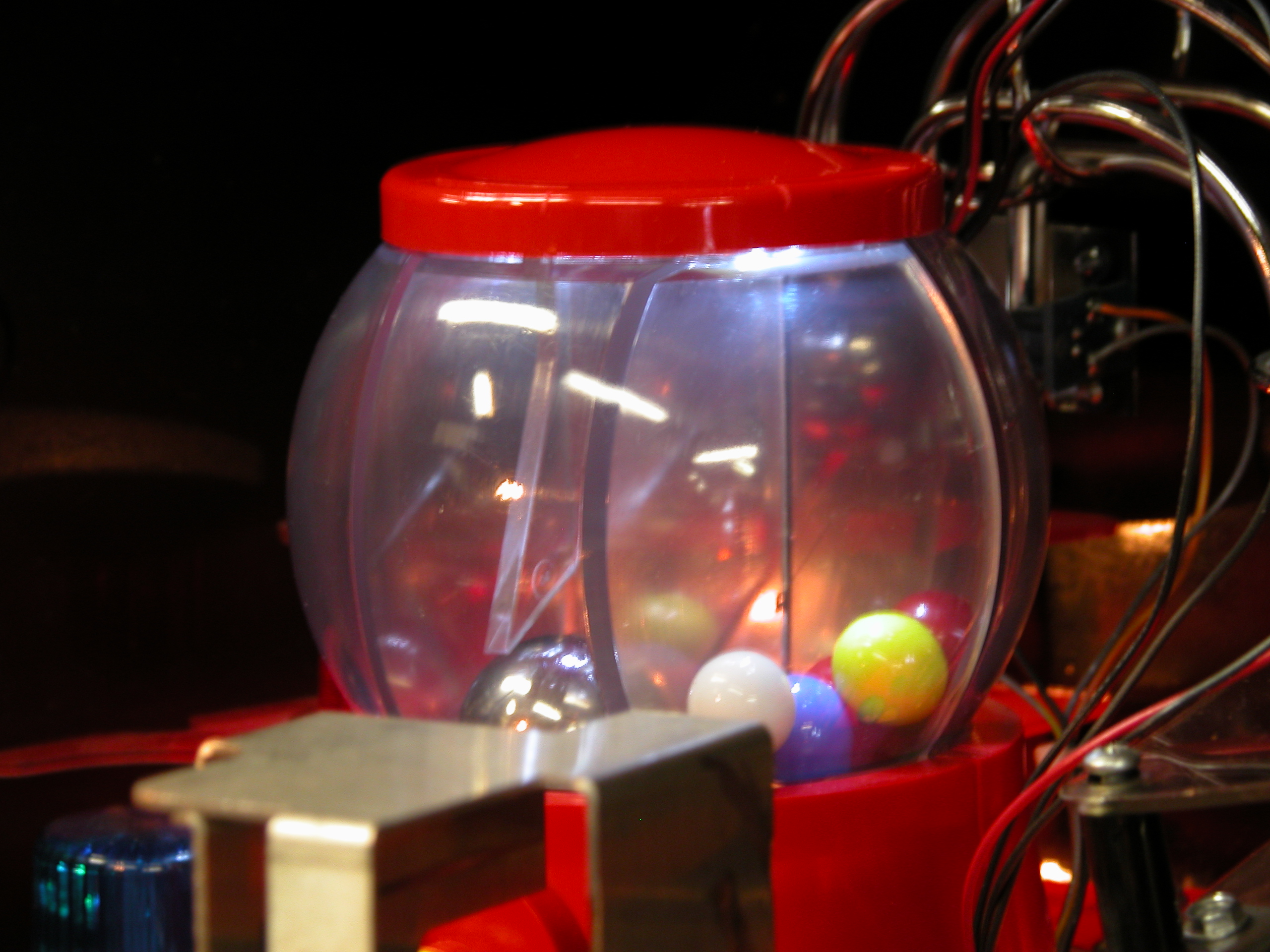
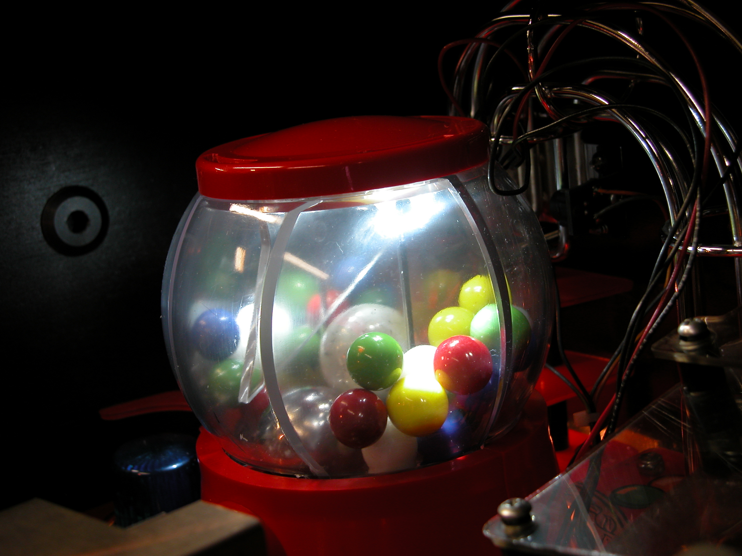
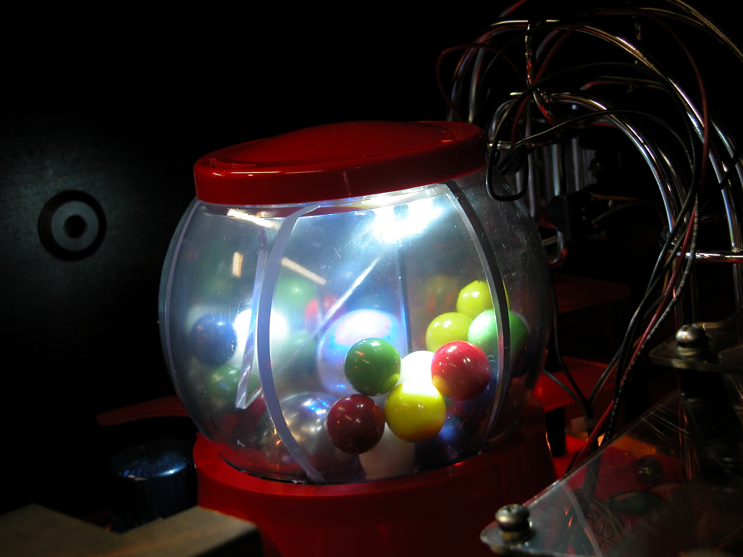
The gumball, unlit under fluorescent light
Side compartment, and both compartments, under fluorescent light
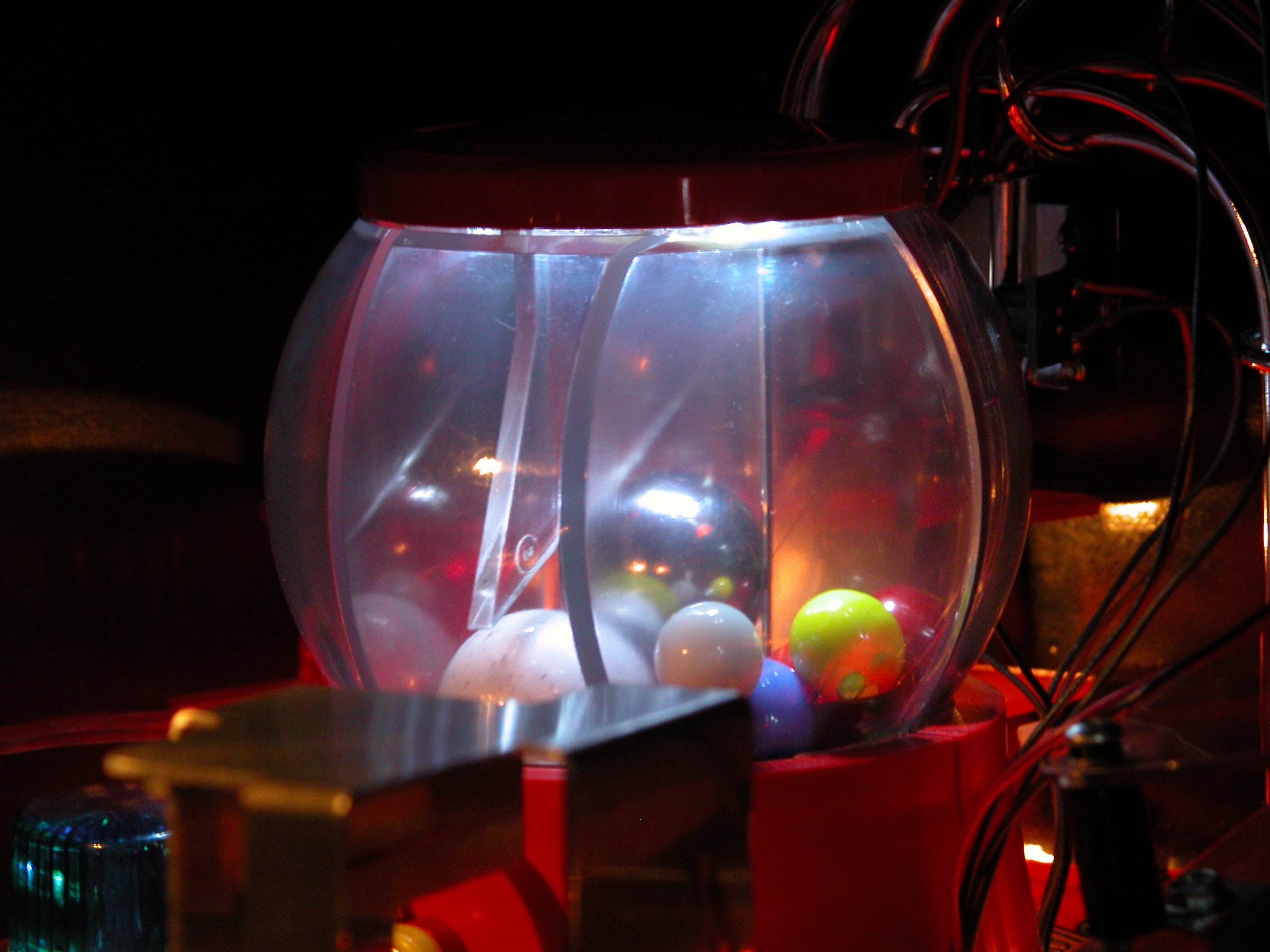
And the side compartment and both compartments with the lights off.
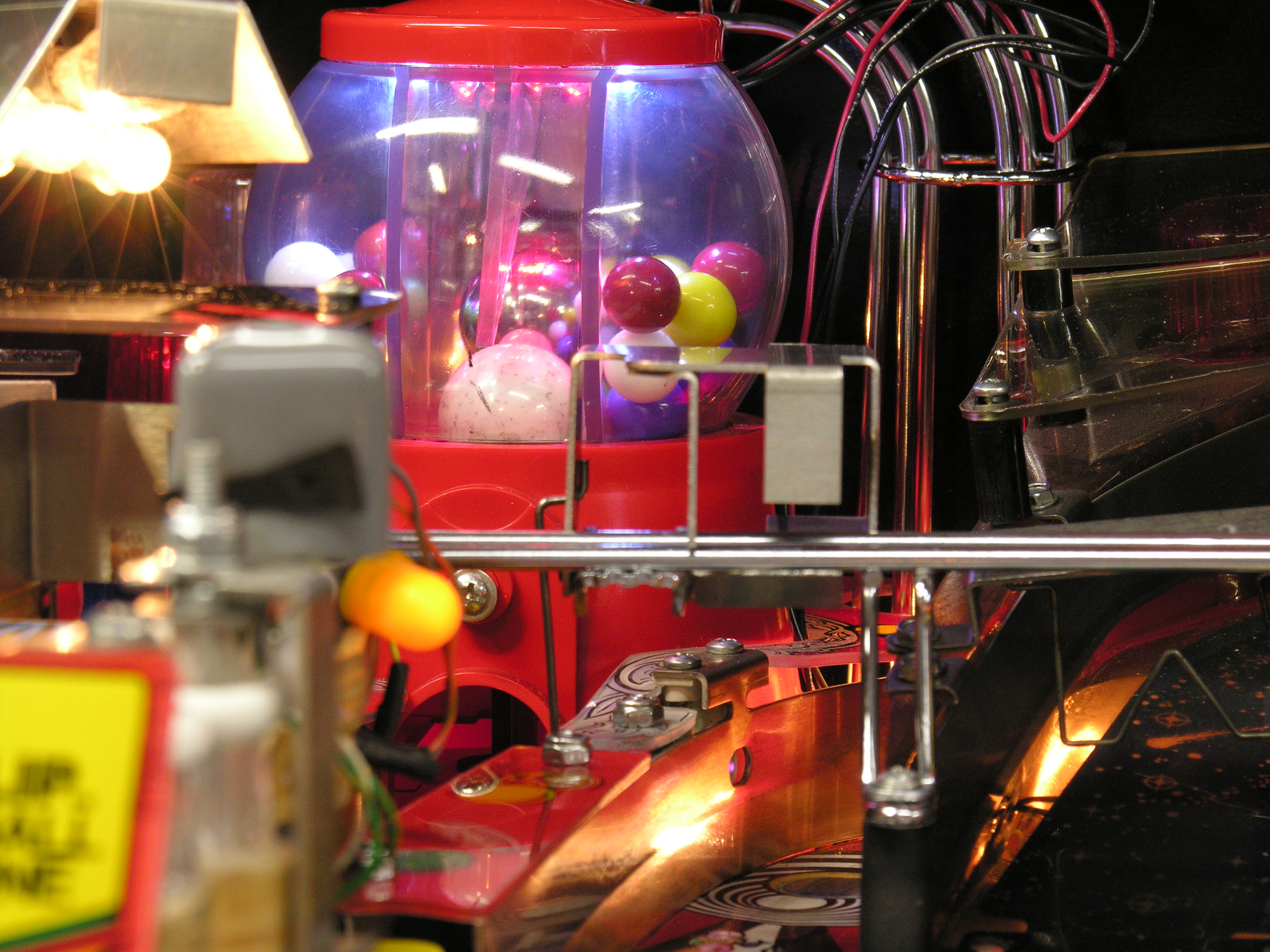
Here's the second board. It has 51 ohm resistors for the sides, and blue LEDs for the center. My camera has quite the thing for blue.
Here is a red version and a green version. In practice, the colors are a little more subtle than you see here. Here's a picture under room lighting that is maybe a bit too subtle.
And the mega version with high-power warm white LEDs and 5mm blue LEDs in the center.
Color Impressions on Christmas Eve 2004
The white sidelights work very well, even under bright room
lighting. Balances
up the lighting at the back very nicely. I still need to try steel gumballs,
although I am not sure that they will look that interesting.
For the center:
White is a bit subtle. Nice if you like it that way.
Blue is quite unique on the board.
Red matches the gumball load light, but my red LEDs are not very bright.
Green is interesting
The colors are most noticeable with the powerball in the gumball. On the steel
balls, they appear as bright pinpoints.
Final Version
I spent some time scoping the resistors and checking currents. The switch matrix spends about 2ms on, and then about 15ms off. So the center LEDs can only be on for about 11% of the time. These are 100mA peak rated LEDs, so there's no risk associated with full current at the 10V or so that the switch matrix delivers. For 100mA peaks we need the following values:
Red 65 ohms
Blue 11 ohms
Green 56 ohms
For the GI LEDs and using white, 27 ohms would be about right. For the ultra high power white LEDs rated at 150mA, 20 ohms will do it. Again, the duty cycle is very light so it is important to peak energy into the lamps. The whole gumball scheme loads up less current than a single bulb on the playfield.
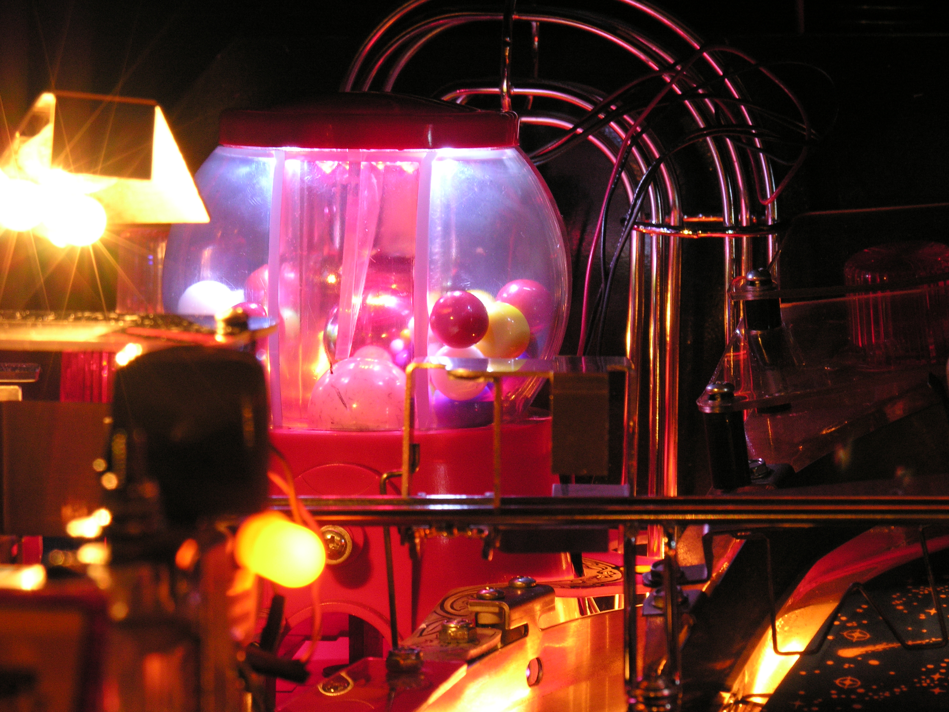
Now, the pictures. My camera REALLY likes strong primary colors.
Playfield view in the light. There's a big fluorescent light right behind my shoulder. The gumball lights just fine. You can see the red bouncing off of the steel ball in the middle. Green is maybe a little brighter, blue a little less bright. They are all obvious.
Final red in the light, closeup.
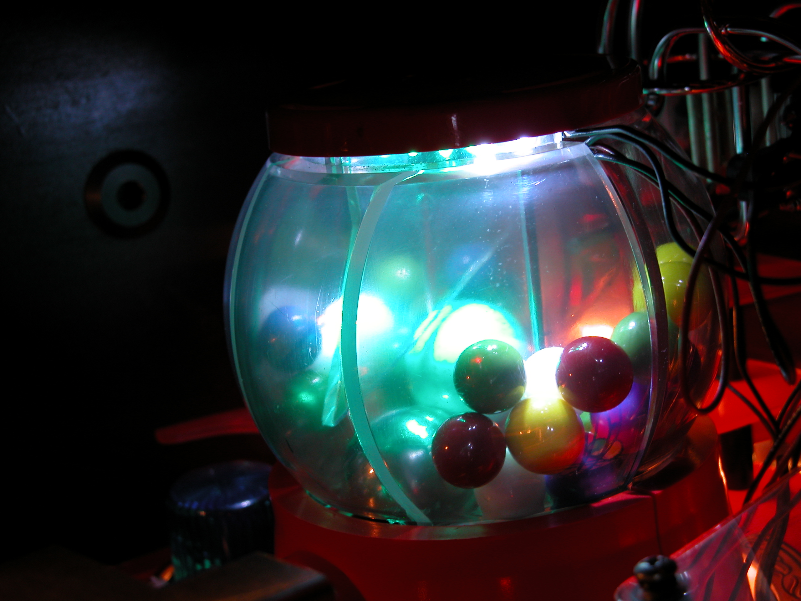
The final version in the dark. This thing is quite bright, and shows off the gumballs well.
Assembly Notes
Put the resistors in first - both sides. The lead from R2 interferes with the gumball separator. R2 is not in the best place: I assumed that it would fit under the gumball cover more easily than it does! A deeper notch in the divider helps.
D1 - D4 need slightly longer leads so that they can be bent out a fraction. The rest of the diodes can be flush. Although I called for 100 ohms all through, I meant to put 51 ohm resistors in the GI circuit to punch the brightness up a bit. I mixed them up, so the 12V circuit is running hotter than it should. I need to check average currents on both legs.
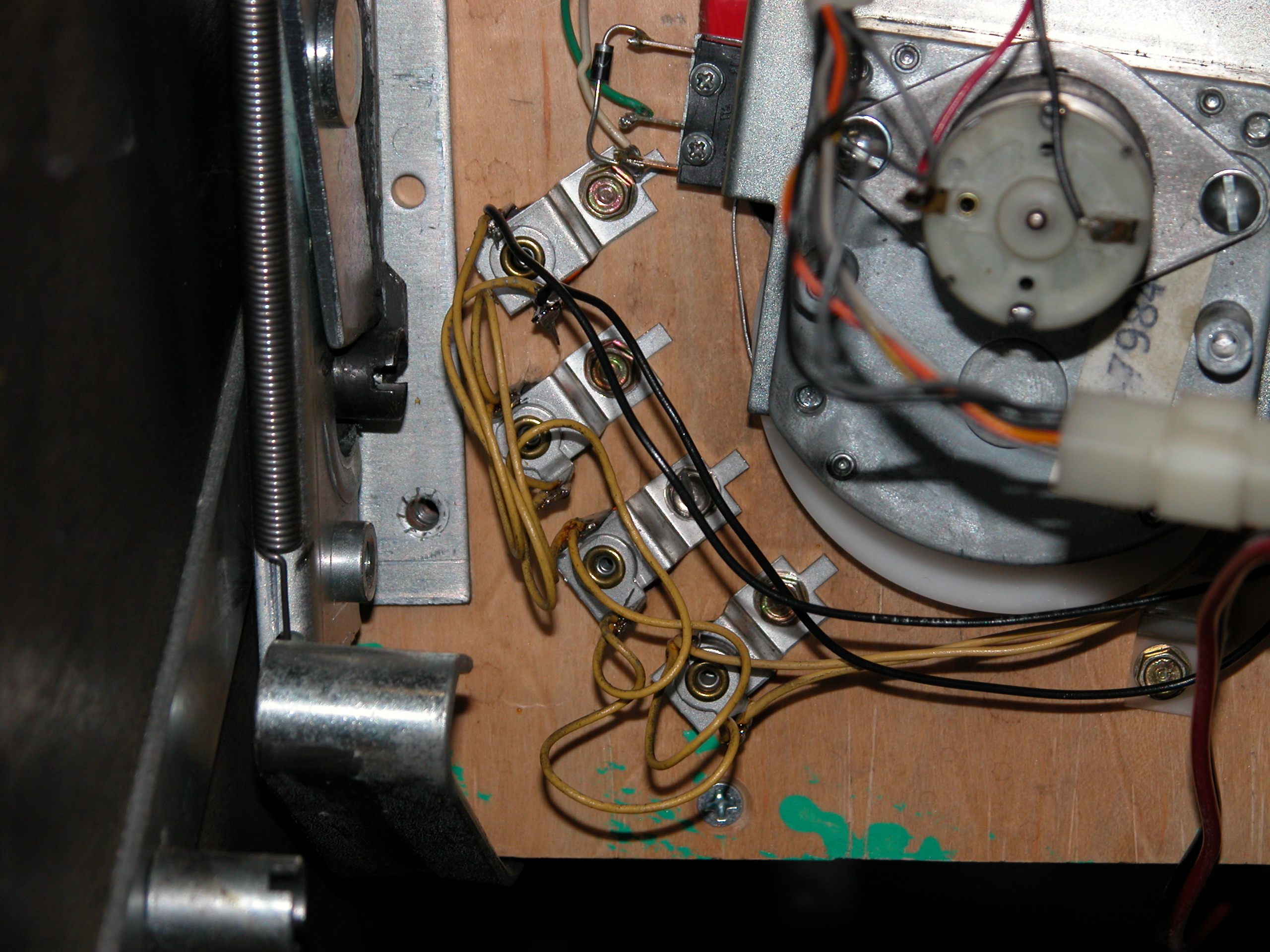
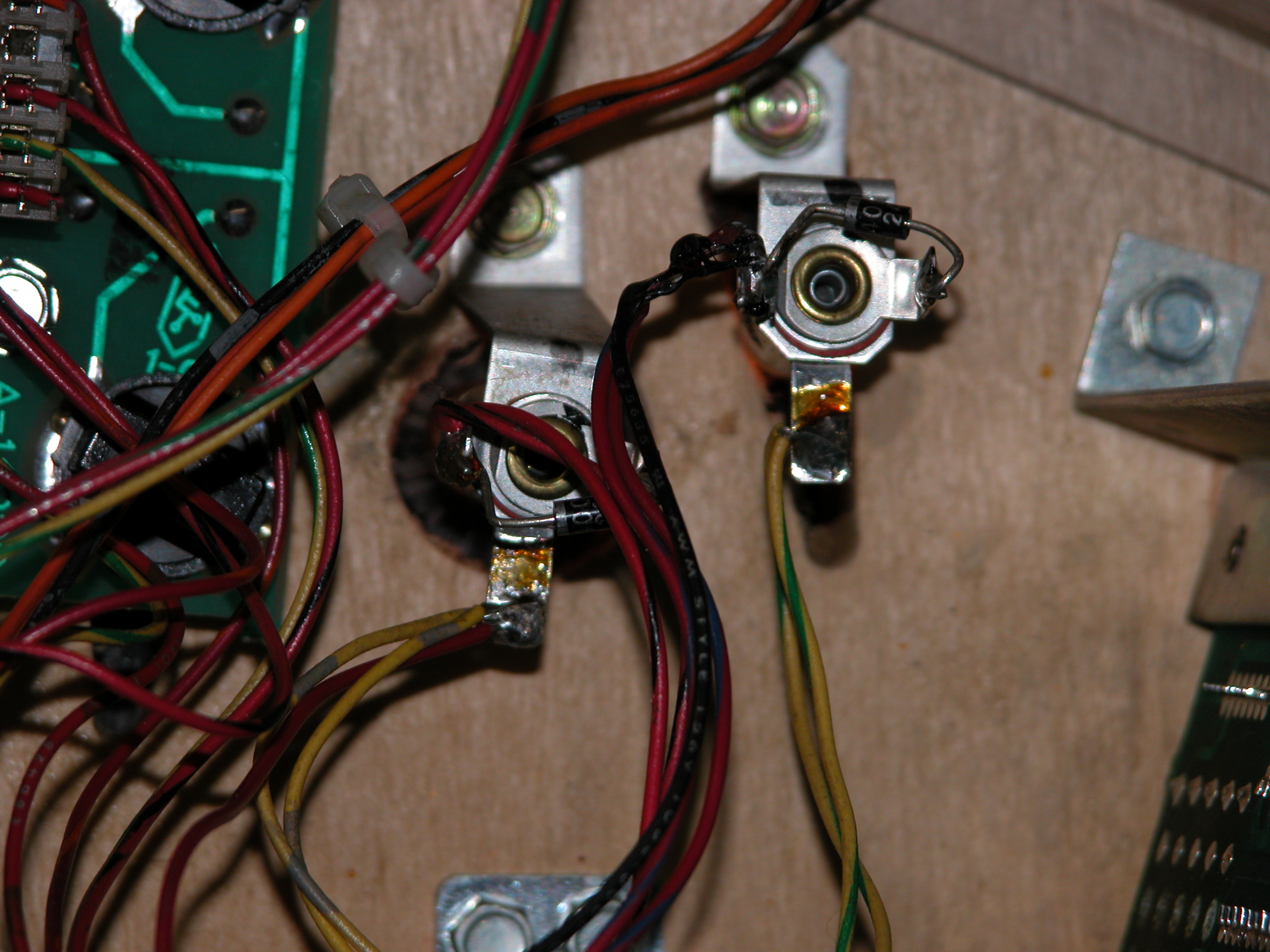
Connections
I soldered to the GI wiring right behind the gumball machine for the side lights. For the "load gumball" light, I picked off the yellow/gray and red/blue circuits from two playfield lights under the table. Here's the whole thing in one shot. I am going to look around for some splice connectors to avoid soldering. The 24 gauge solid wire is too stiff: hard to get it to look right. I need to find some stranded, and maybe duck back to 26 gauge. There should also be a disconnect under the playfield, so that the wires can be tied to the ball guide.
Things I Would Do Differently Next Time
Better Layout
I would like to get R3 and R4 onto the top side of the board. This approach reduces the size of the cutout in the gumball divider.
Better Power
Using the 6.3VAC is not such a great way to go, even though it seems to work OK. The problem is that the AC cycle just doesn't leave a lot of room for the LEDs. I think that a little rectifier, a small capacitor, and two LEDs in series would be nicer. Should be brighter and show no flicker.
I do like the 6 LEDs in the center compartment. There's no concern about seeing that the lights are on, even under the bright fluorescents in my garage.
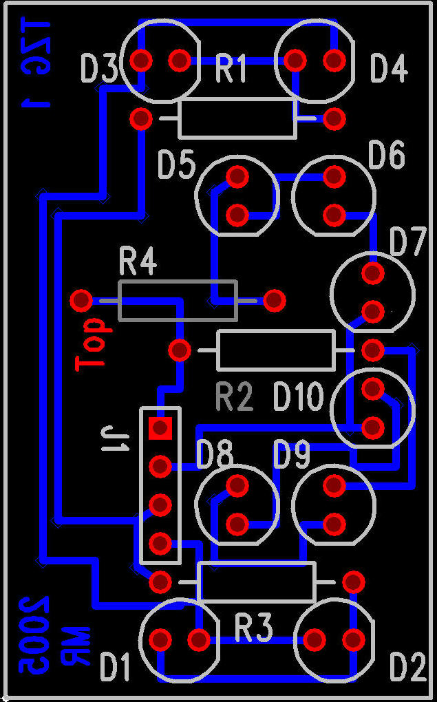
Here's my first layout. I didn't like the power connector hanging off of the edge of the board, so I pushed everything around a bit to make room. The new layout is a bit cramped, but it does bring the light toward the front. I also rotated the side LEDs so that they can be bent outwards a little.