The Clock Project Page
In the original design, the four lights in the clock - one for each quadrant - were individually controllable. This design would have allowed for some neat effects. For example a dark clock except when a clock mode was active. Or, a rotating light effect in timed modes. Anyhow, the designers ran out of light circuits so they shoved it onto the GI which opened up all of those clock heat problems. They do flash the clock in timed modes.
I am scheming about adding some more LEDs to the clock. Red, green, blue and white in each quadrant. I should be able to add some neat effects - colored strobes in the last 15 seconds of timed modes, for example. I can deduce what effect to deliver by the motion of the clock.
However, to do this I have to redesign BOTH clock boards. Well, I could leave the hours board alone, but the original Williams design is a bit iffy and it would be nice to get away from the special optos.
Clock Rules
Normal Gameplay: 12 noon
Most timed modes: wind from 12 o'clock to 12 o'clock.
Stacked timed mode: rewind back to 12 o'clock and then run forwards to 12 o'clock. Underlaid mode continues to run. (question: who takes priority?).
Clock chaos: wind back to 6. ind back to 12. reverse direction on a hit. Stop when the hands hit 12.
Ball drain: hands to 12
Attract mode: show the current time
Design Process
So the first thing is getting the mechanical design sorted out, and duplicating the basic electronics. Then, we'll design the next phase. There are some peculiarities in the original design.
First, we all know about the GI lamps, four #86 bulbs that cook up the inside of the clock. This heating damages the plastics and makes the clock electronics compartment into a hostile environment. One consequence of this is degradation of the optocouplers, which combines with the switch circuit problem to cause premature failure of the clock.
Less obvious is that the power design for the optocoupler LEDs is not efficient. The LEDs only require 1.2V to do their work, but the supply delivers 12V. Therefore, there is a 470 ohm resistor in the LED circuit to drop the 10.8V that we need to get down to 1.2V. This corresponds to a drive current of 23mA - a little above spec. However, the resistor is dropping 10.8V at 23mA, which is 250mW. There are eight of these in the clock, that is another 2W of heat - and it explains why the resistors are often burned up. They get really hot. Without the GI heat they could be OK, but this is an iffy design. A better approach is to wire the optocouplers in series, and have a single resistor dropping the 7.2V that we need. That's 360 ohms. I could run all 8 in series, but that would make the new and old boards incompatible with each other.
The third problem is the sense circuit, which makes the whole heat problem worse. It is why we need special sensitive optos. But this is the hand that we are dealt.
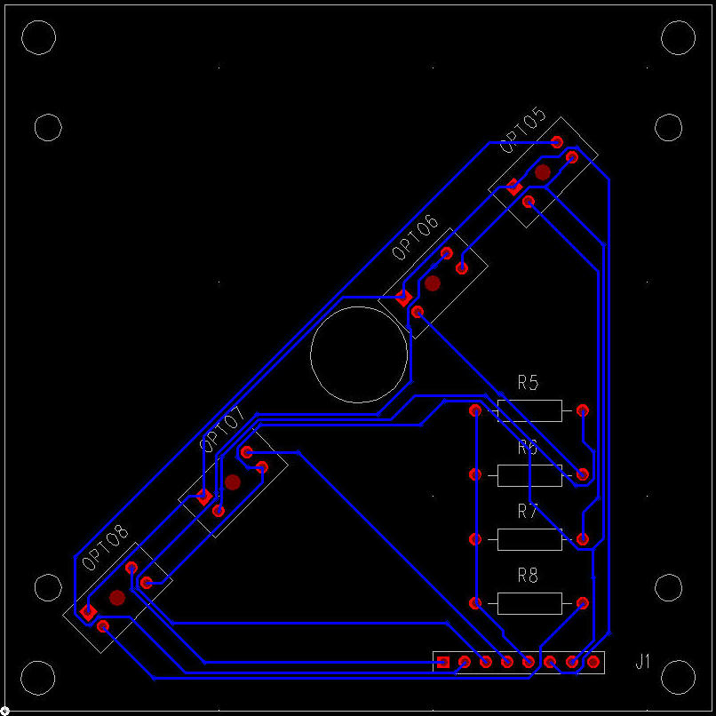
Here's the hours board. This is mostly done; it follows the original schematic. For some reason, the WIlliams optos use a different pinout to the ones that I have found. It is a simple change - the device is rotated 180 degrees - but this could certainly mess you up! The good news is that Williams explicitly labeled the anode, cathode, collector and emitter pins. Note that J1 has one pin too many. This is on the todo list.
There's a lot of open space on this board. I could put quite a lot of stuff on here, except I don't want to lose backwards compatibility. Make the whole clock light up, maybe? Perhaps there is a use for that extra pin!
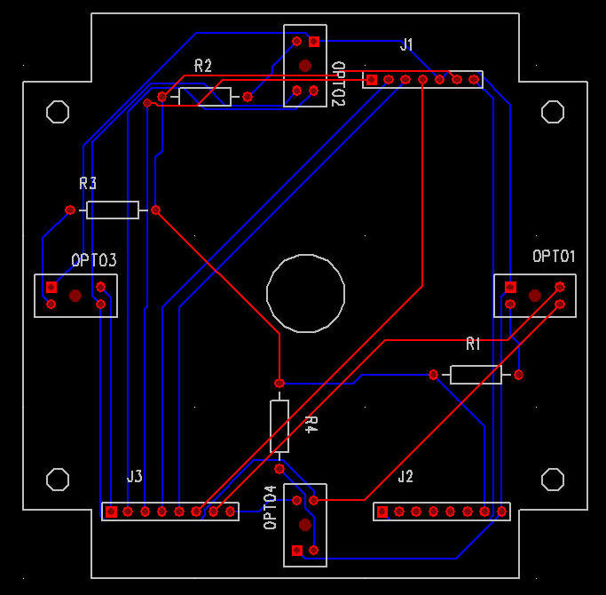
Here's the first draft of the minutes board. This is mostly as Williams designed it, but it does not yet have lights. Opto 1 is placed backwards; this needs to be fixed.
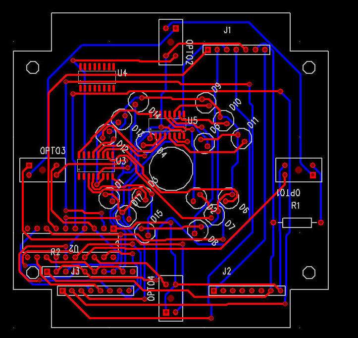
Here's the latest version. It has lamps and drivers. This version also uses a CMOS latch to get away from the opto level issues, and allow me to read the optos from the microprocessor. The design is going to need a 5V buck regulator, which will have to go on the hours board: I am running out of PADS resources! The microprocessor is not connected, no decoupling, and power and ground missing in action.
You can see the 16 quadrant LEDs in the center are of the board, with their Maxim LED drivers. The microcontroller is largely disconnected, and is currently in the top left. The latch and pullups are in the bottom left hand corner. I can add exactly one more part: probably the clock oscillator for the PIC. Decoupling caps will have to be opportunistic.