Fixing the WPC-95 GI Diodes
When Williams switched to WPC-95, they dropped from five controlled GI
circuits down to three. They replaced two of them with always-on GI, eliminating
two heatsinks and triacs from the board. A triac causes a voltage drop, so
Willams inserted four diodes in each alwasy-on circuit in a series-parallel
arrangement to reduce the GI voltage. Presumably, they did this to extend bulb
life. But they didn't figure out that the diodes would make as much heat as the
triacs - which have great big heatsinks. So the diodes get hot, and burn up the
PCB. It blackens and delaminates. Williams eventually switched out the diodes
for zero-ohm resistors. Here, we look at how you can easily remediate a bad
board with just two wires.
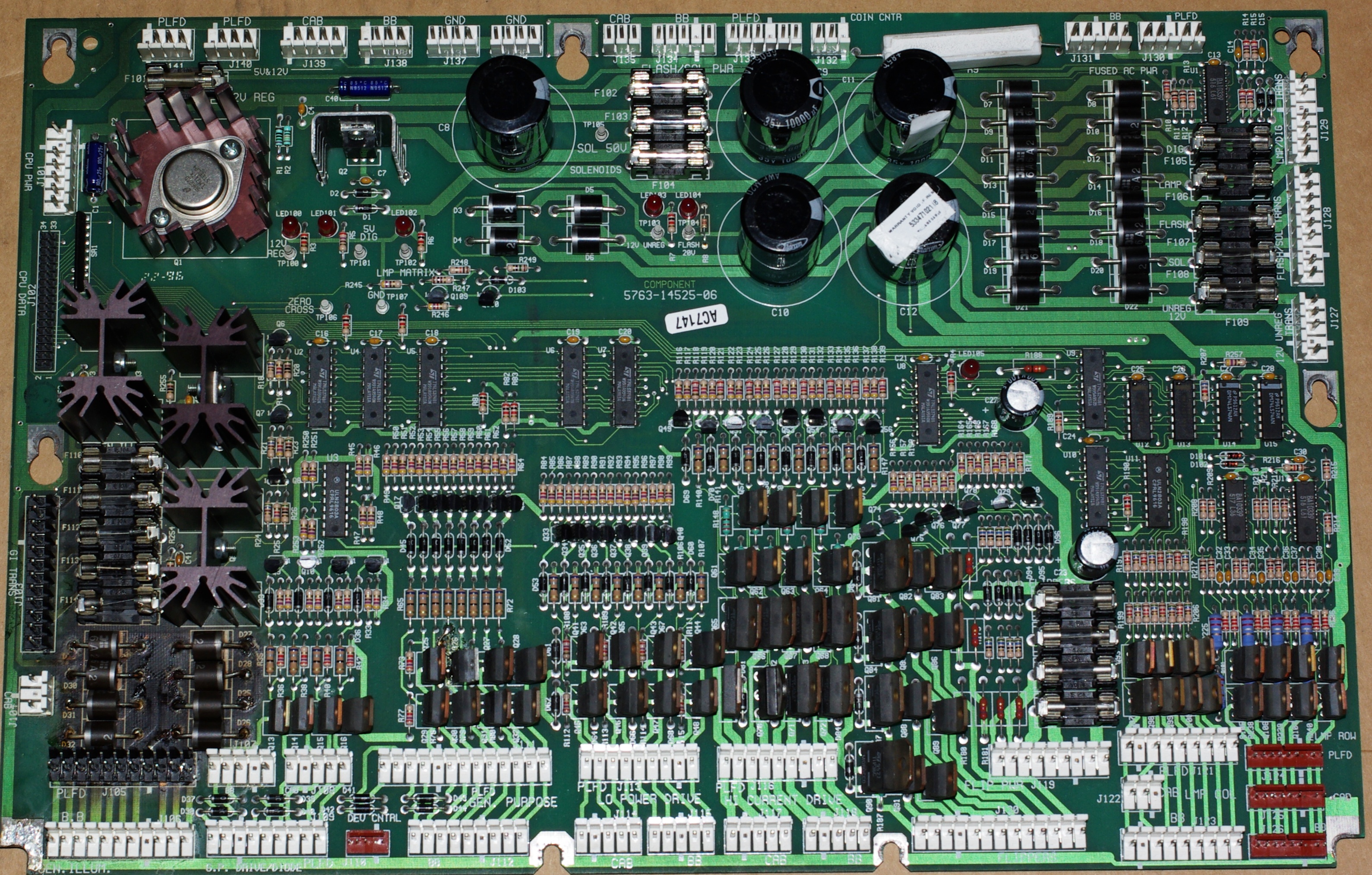
The diode jumpers are equivalent to the following connections:
J103 pin 11 to J105 pin 5
J103 pin 12 to J105 pin 6
These connections can be reversed if you are soldering from header to header:
it makes a tidier layout. You can jumper from header to header, across the
diodes, or from diode in to header. The jumper will depend on how good the PCB
is.
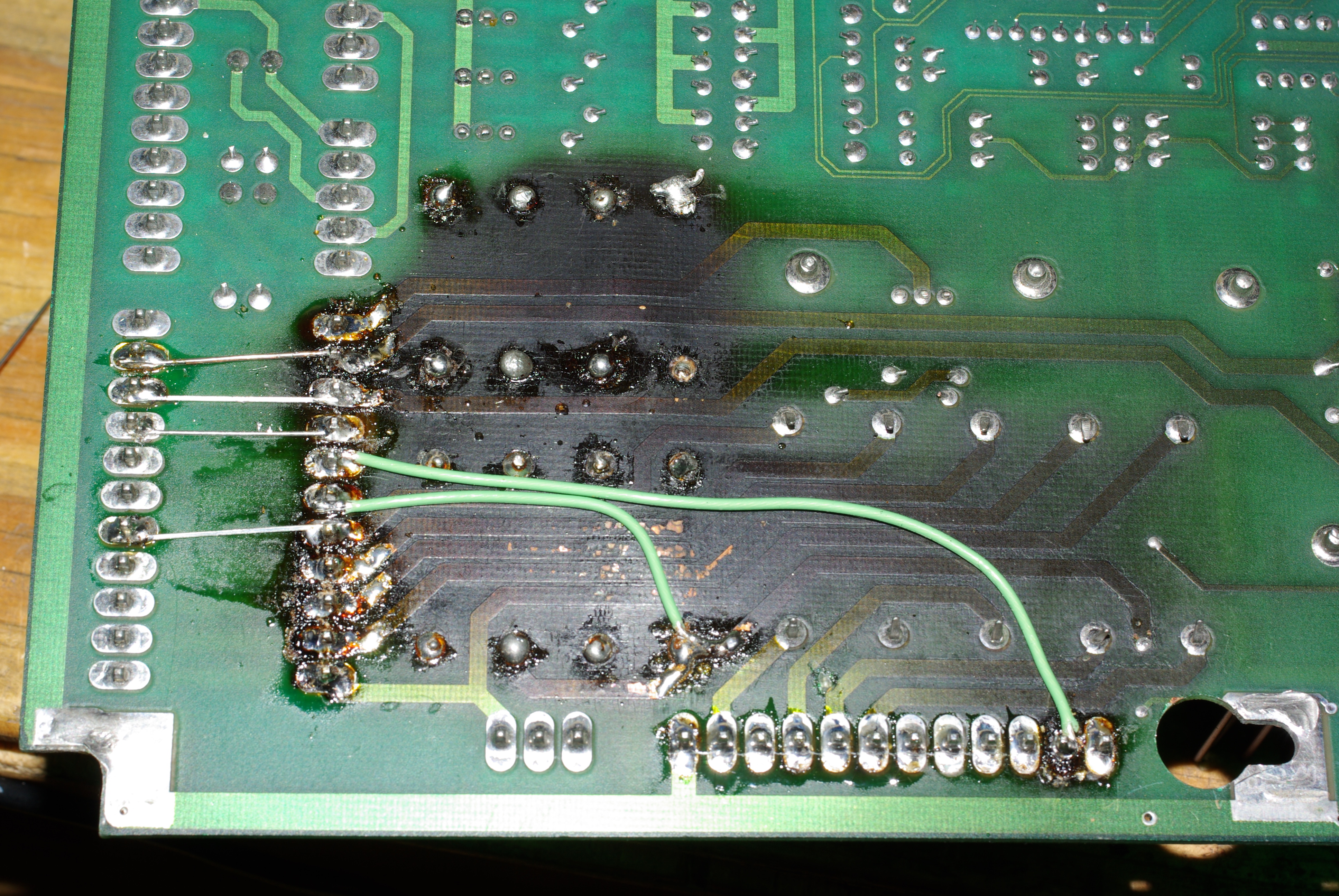
 Here
is a repair using one header-to-header jumper, and one diode in to
header jumper. The header-to-header is always guaranteed, and completely
bypasses the diodes. Here
is a repair using one header-to-header jumper, and one diode in to
header jumper. The header-to-header is always guaranteed, and completely
bypasses the diodes.
The best wire to use is solid core 22GA. Plenty thick enough for the
current, and it will hold its form well. 22GA stranded is a good
alternative. Thicker wire is unnecessary, and harder to solder neatly.
For a full header to header repair, the other wire would go to the
end pin on the input connector, adjacent to the other jumpered pin. |
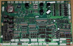 Here's
the top side of the board, showing the cooked out diode area. Here's
the top side of the board, showing the cooked out diode area. |
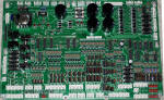 And
a brand new board, showing the factory jumpers. And
a brand new board, showing the factory jumpers. |
 Here
is a repair using one header-to-header jumper, and one diode in to
header jumper. The header-to-header is always guaranteed, and completely
bypasses the diodes.
Here
is a repair using one header-to-header jumper, and one diode in to
header jumper. The header-to-header is always guaranteed, and completely
bypasses the diodes.
 Here's
the top side of the board, showing the cooked out diode area.
Here's
the top side of the board, showing the cooked out diode area.  And
a brand new board, showing the factory jumpers.
And
a brand new board, showing the factory jumpers.