Installing the Gumball Lamp Board
There's only one tricky thing, The unit you receive will have the board and both harnesses connected together into a complete assembly. It has been tested to work like this. The only thing to watch for is the connector on the lap board; you should be looking at a flat white surface. If you remove it, you will see four "windows" in the plastic, through which you can see the connector pins. Just remember, these windows are supposed to face the circuit board.
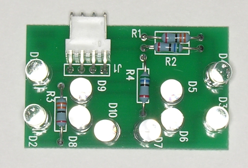
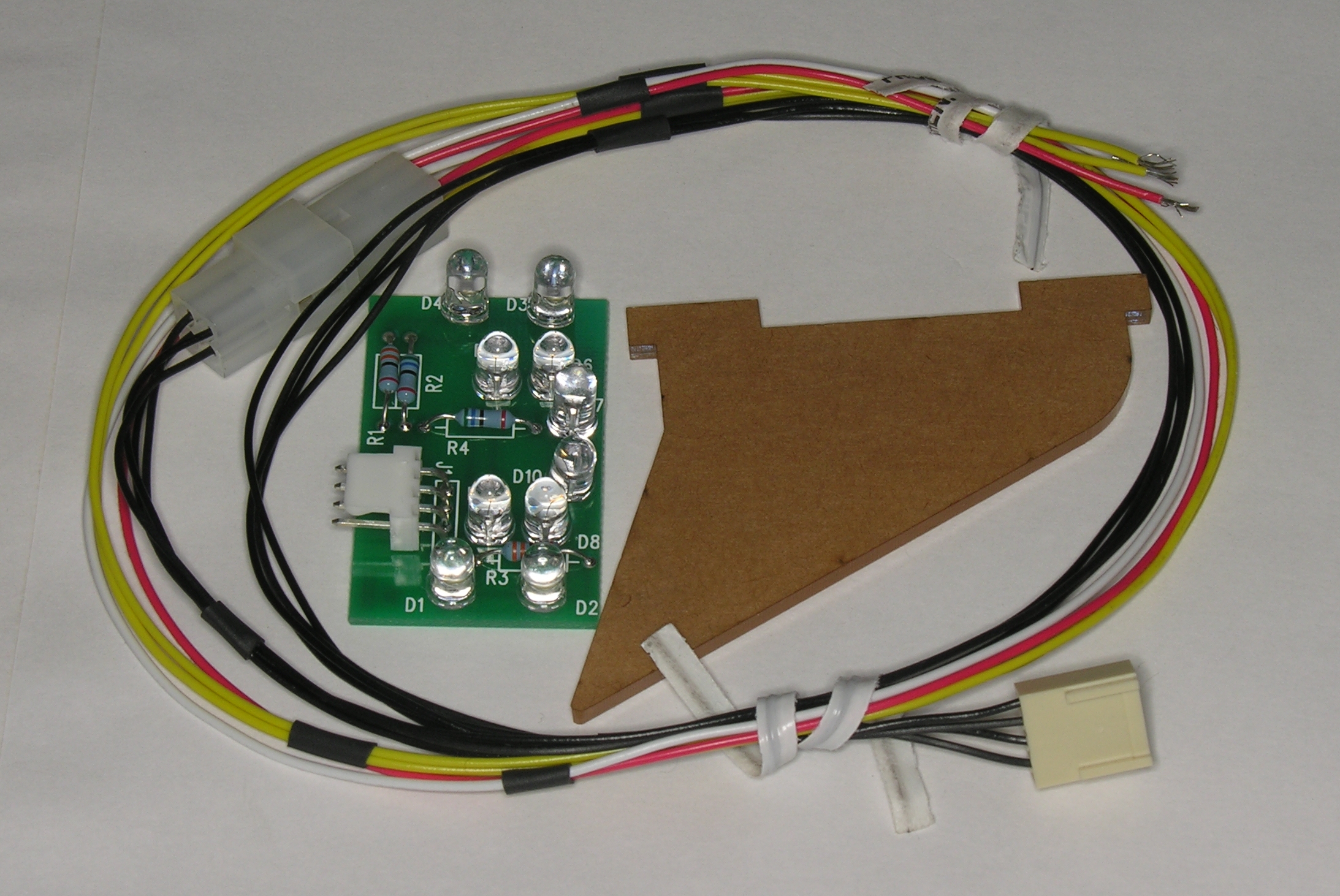
The Board
Here's the latest version of the board. It uses 5mm LEDs, which are a bit tighter from an installation perspective but are quite a lot brighter than the 3mm versions. The kit includes the wiring harness and a notched gumball divider plastic, as well as a few black and a few white tie-wraps. Note that the plastic still has its protective brown sticky paper cover on it.
Step by Step Installation
First, turn the machine off and remove the glass from the machine. Next, loosen the playfield plastic by the right hand side of the gumball machine. I removed the front nut and loosened the rear nut so that I could open up a small gap. We do this to make it easier to feed the wiring through later.
Now, raise the playfield. We are going to be working on the lower left corner, in the gumball area. Here's a picture, with key locations picked out. You'll see three areas: "the passthrough hole"; the "Load Gumball" connection; and the GI connection area.
Start off by placing the Molex playfield disconnect near the passthrough hole. You'll want a couple of inches of slack so that it is easy to pull the connector apart when removing the gumball feed tube from the machine. Once it is in the right location, use a white tie-wrap to hold it in position against the wiring harness. Next, route the two yellow wires over to the GI connection area, following the wiring . Then, route the red and black (earlier harnesses have a white wire) up to the "load Gumball" connection area. Use white tie-wraps to put the wiring in place. Make it as tidy as your taste requires.
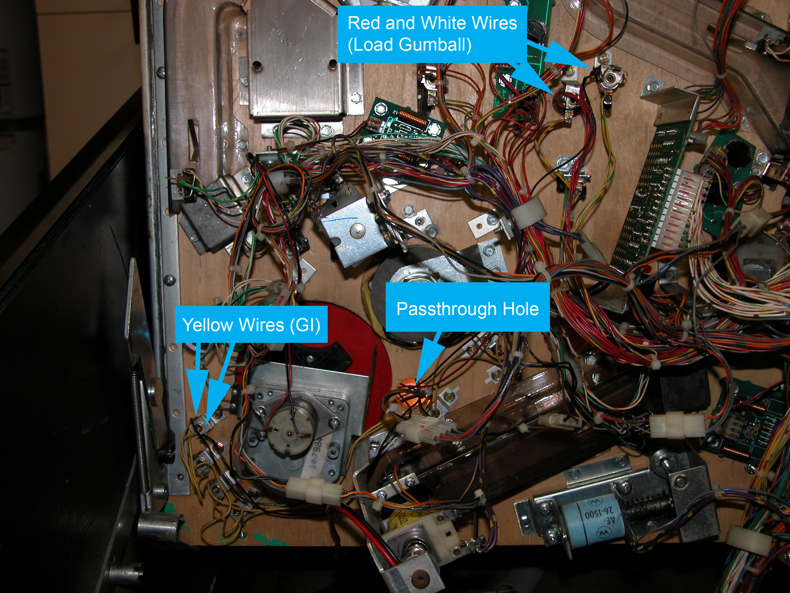 Here's an overview of where everything goes under the machine. |
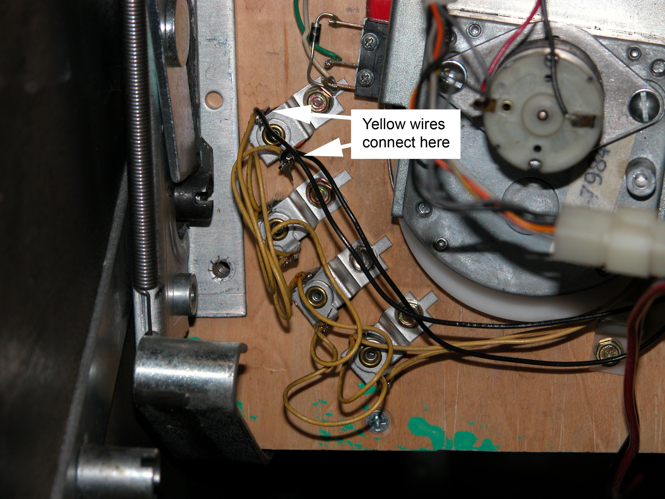 Next, cut, strip and solder the yellow wires to the GI connector. In the
picture, they are the black (yes, yours are yellow) wires on the lampholder under the "GI Connection"
box. You can connect to any convenient GI socket. Next, cut, strip and solder the yellow wires to the GI connector. In the
picture, they are the black (yes, yours are yellow) wires on the lampholder under the "GI Connection"
box. You can connect to any convenient GI socket.
(Click to get the super detail picture) |
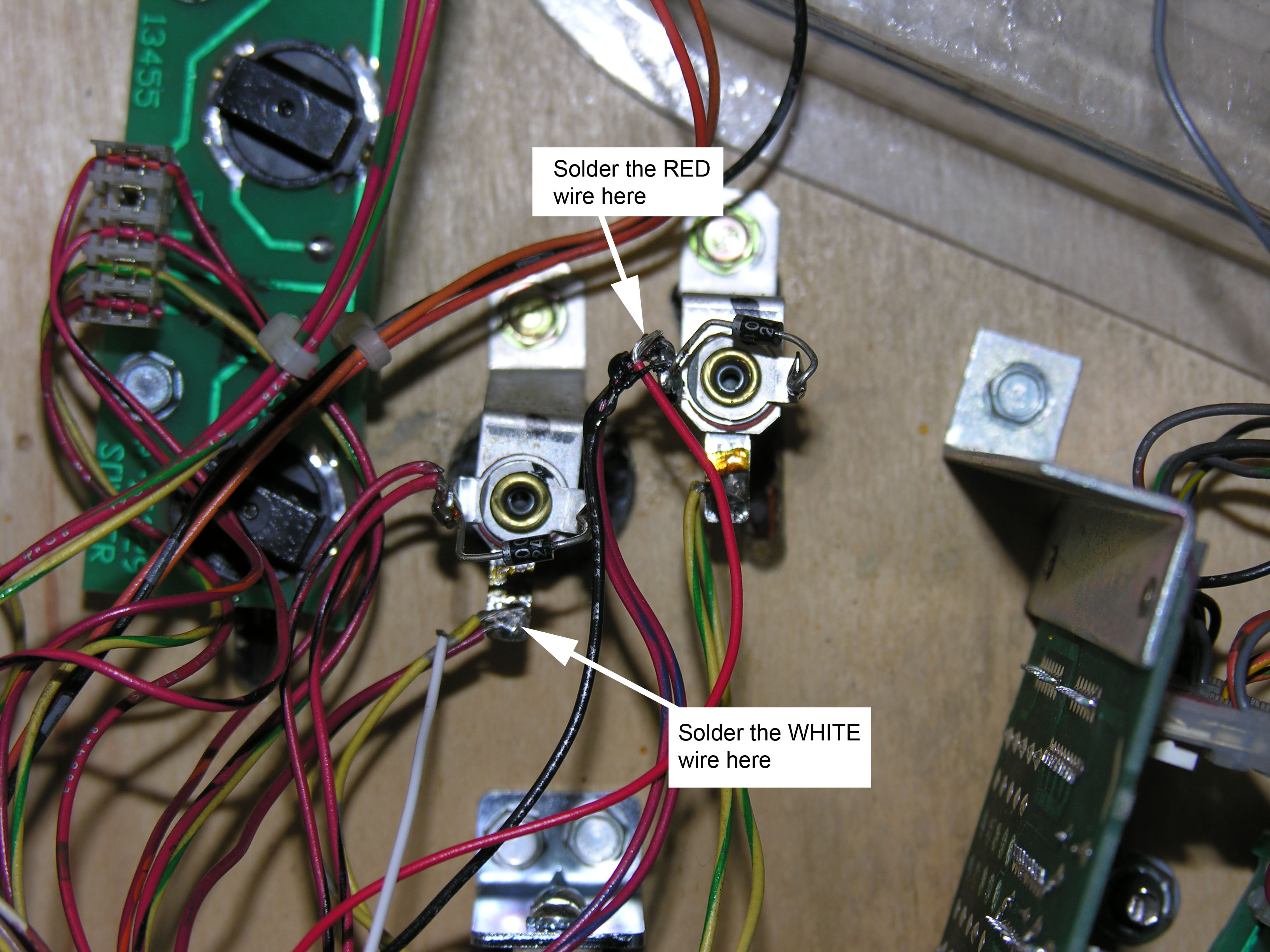 Next, connect the RED wire to the RED/BLUE wire on the bulb on the right. The
BLACK (or maybe WHITE) wire goes to the YELLOW/GRAY wire on the bulb on the left. These are the
same wires that go to the "Load Gumball" light - they are easier to get to here.
You can probably do a neater job soldering than I did. Next, connect the RED wire to the RED/BLUE wire on the bulb on the right. The
BLACK (or maybe WHITE) wire goes to the YELLOW/GRAY wire on the bulb on the left. These are the
same wires that go to the "Load Gumball" light - they are easier to get to here.
You can probably do a neater job soldering than I did.(Click to get the super detail picture) |
Finally, merge your connections into the wiring loom using white tie-wraps.
We're done with the electrical work. Before we complete the assembly, we'll do
an under-the-playfield test. If you disassembled the connectors, put them back
together. The Molex four-way only goes together one way. The white board
connector should have the blank side facing up; you should not see the four
connector "windows", they should be underneath, facing the board. Make sure that the pins are all
aligned properly; offset pins can damage the LEDs.
Now, place the board inside the cabinet, on an insulator such as the wooden
bottom. Get the LEDs to face up so you can see them. One last check for wires,
tools and so on, particularly around where you were working, and turn the
machine on.
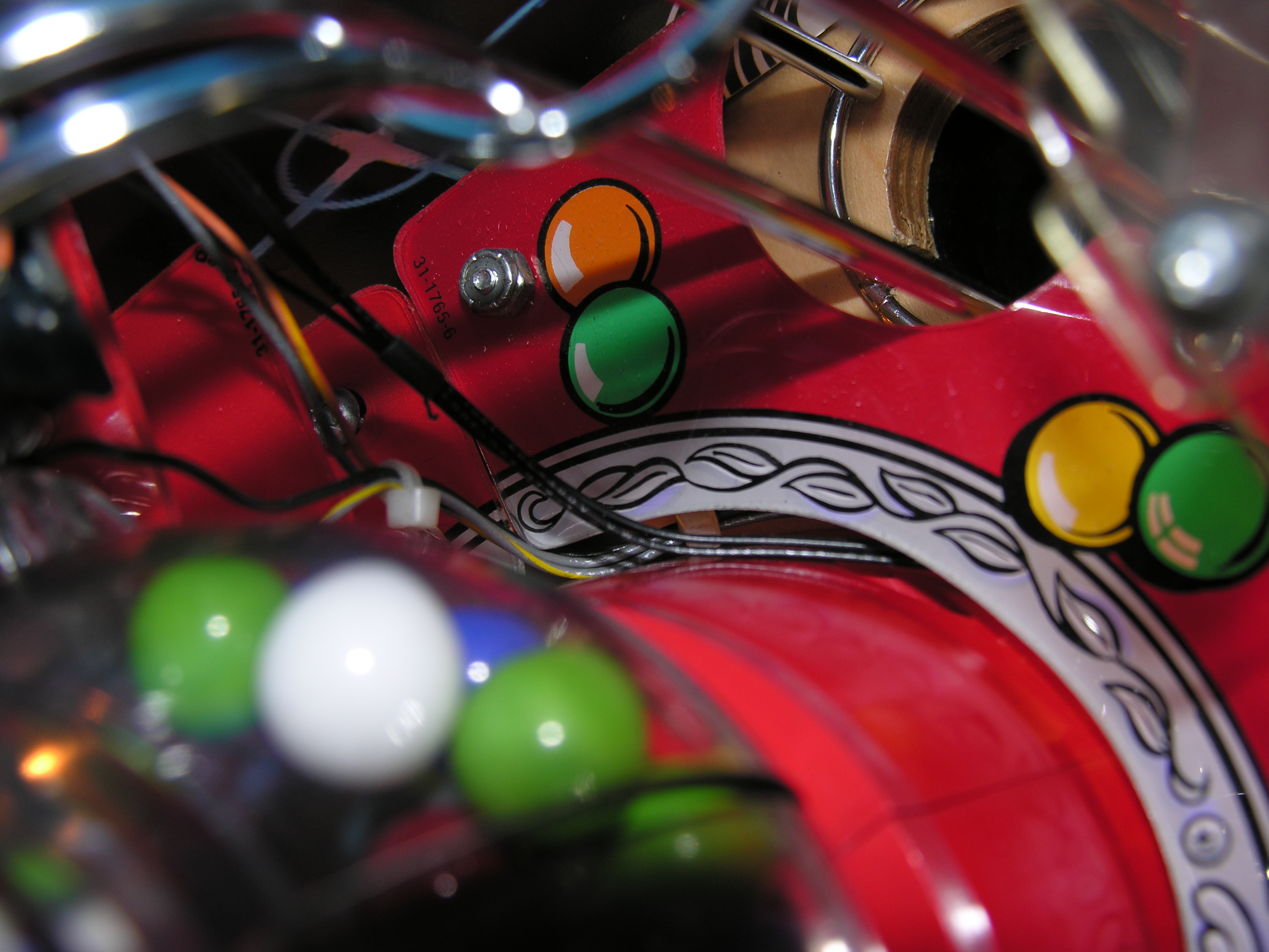
Once it completes the test cycle, it will light the GI and the white lights will
come on. A few seconds later, it will start the attract cycle and the center
lights will start flashing. They should all be rather bright, so that you don't
want to look at them straight on. If all is well, turn the machine off and
disconnect just the board.
Next, feed the board connector and wiring up through the access hole.
Your goal is to get it past the gumball plastic. Once successful, lower the
playfield and put it back into the machine.
You should now see the board connector and wiring on the top of the playfield.
Slide it around to the back of the gumball, and feed the connector up and into
the gumball connector from behind. The wires feed through the square hole in the
top rear of the gumball globe.
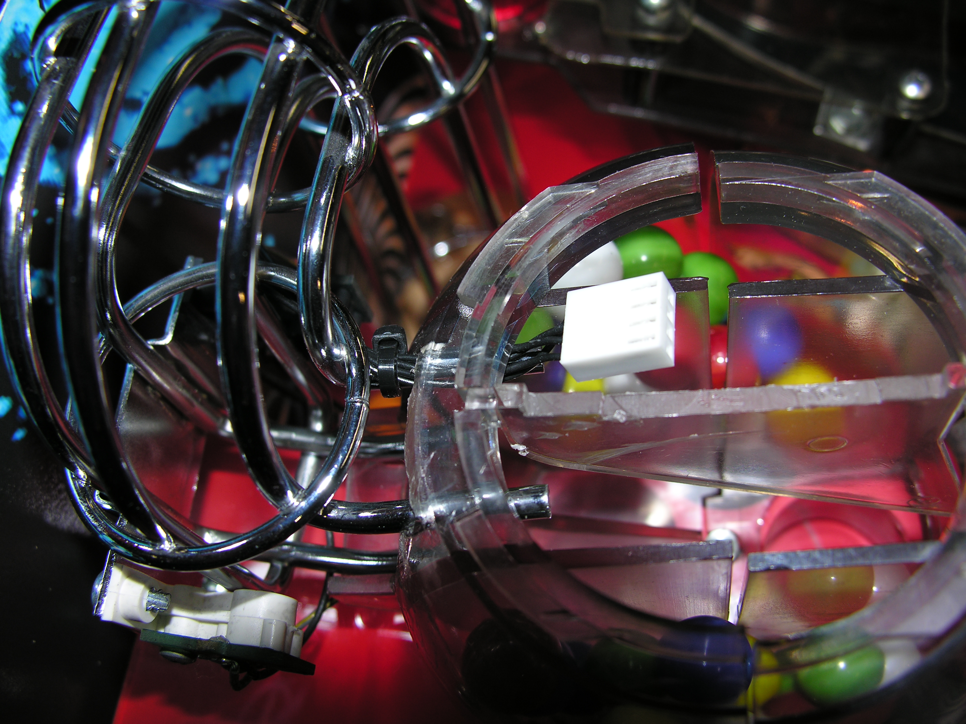
It is important to keep the wiring out of the ball path. Here's a picture of how
it should look installed. Once it sits right, use a black tie-wrap to tie it to
the top right ball guide wireform. Run the wiring behind the gumball, following
the path of the opto wiring. Once it sits right, tuck any excess under the
plastic and fix it down. Note that the connector "windows" face up away from the
playfield.
Next, remove the gumball divider from the gumball.
Here's a picture of the wire disappearing under the gumball plastic.
Finally, put the new notched gumball divider back into the machine. Lift the connector up so
that it stands vertically, and push the board onto it.
Make sure that the pins align, and that you cannot see the connector "windows".
Swing the board down into the notch on the divider. The board is a tight fit,
the middle leds squeeze onto the divider. You may have to push a bit. Finally, replace the gumball lid and put the glass back
on. You are done!