 Here's
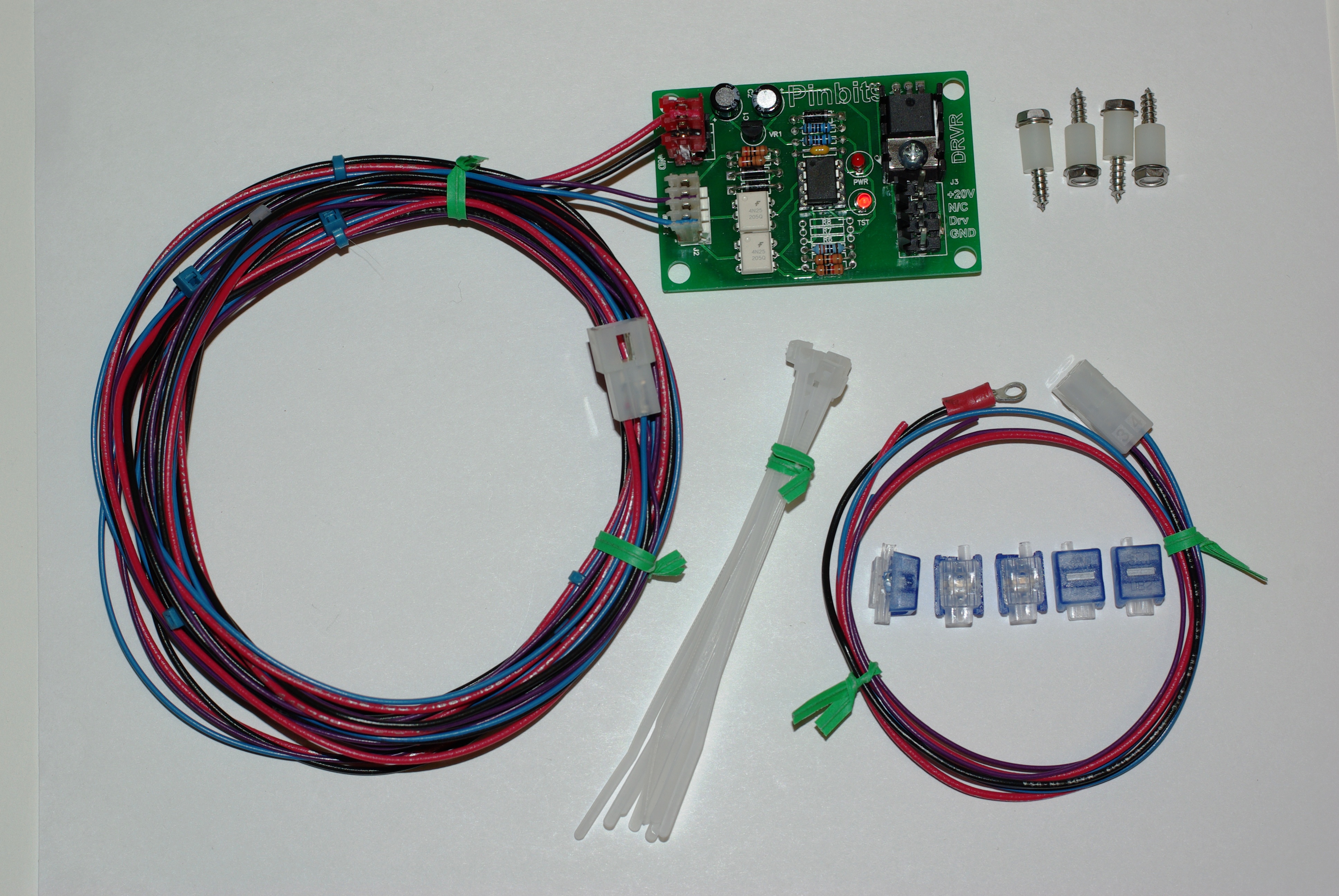
the complete kit. The board and cabinet harness; the head harness;
screws and spacers; wire ties; and five clip connectors. The current
version has slightly different connectors on the board, but
installation is the same. Here's
the complete kit. The board and cabinet harness; the head harness;
screws and spacers; wire ties; and five clip connectors. The current
version has slightly different connectors on the board, but
installation is the same. |
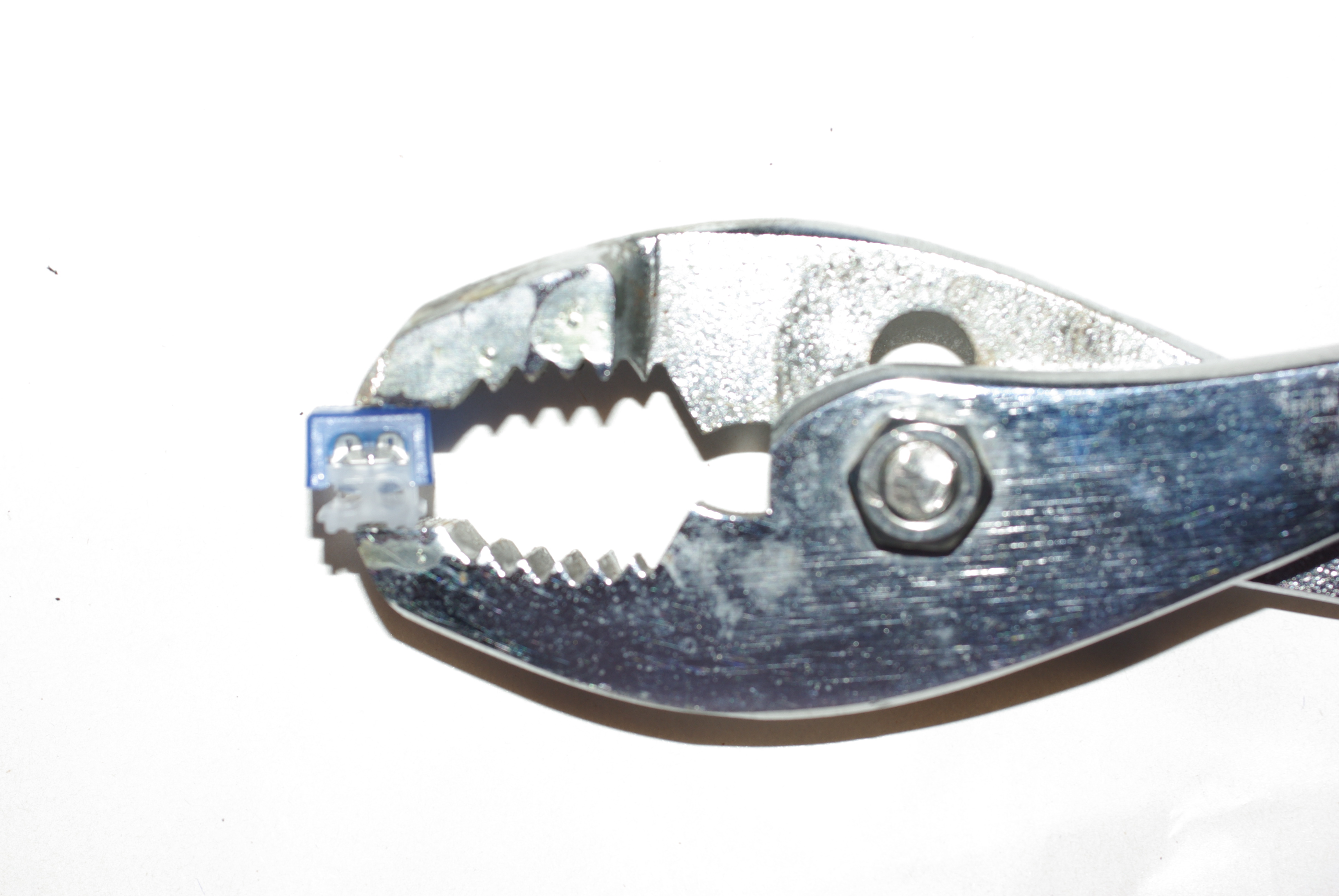 The
connectors are designed for telephone applications, but work well
for the shaker motor. These connectors close with a pair of slip
joint pliers. Robogrips will also work, as will a small C clamp. The key is that the jaws are
roughly parallel before they close. make sure that the connector is
centered in the jaws, and then squeeze it flat. The
connectors are designed for telephone applications, but work well
for the shaker motor. These connectors close with a pair of slip
joint pliers. Robogrips will also work, as will a small C clamp. The key is that the jaws are
roughly parallel before they close. make sure that the connector is
centered in the jaws, and then squeeze it flat.It is to use parallel pliers. Regular pliers will tilt the connector cap, and then you won't get a good connection. We tested these connectors on pinball wire - properly installed, they will easily carry 5 amps. |
| Start off by installing the board in the cabinet, by the tilt mechanism. Use the four screws and spacers to fix the board to the cabinet. Set the harness connection towards the top, and run the wires with the cabinet harness up past the grey flex wiring tube. Connect the shaker motor to the bottom connector. |
 Put
the playfield upright, and fish
the wires up over the back of the playfield. Then lower the playfield
to the high rest position. This position lets you reach underneath
the head. Put
the playfield upright, and fish
the wires up over the back of the playfield. Then lower the playfield
to the high rest position. This position lets you reach underneath
the head. |
 Next,
fish the harness into the backbox. Next,
fish the harness into the backbox. |
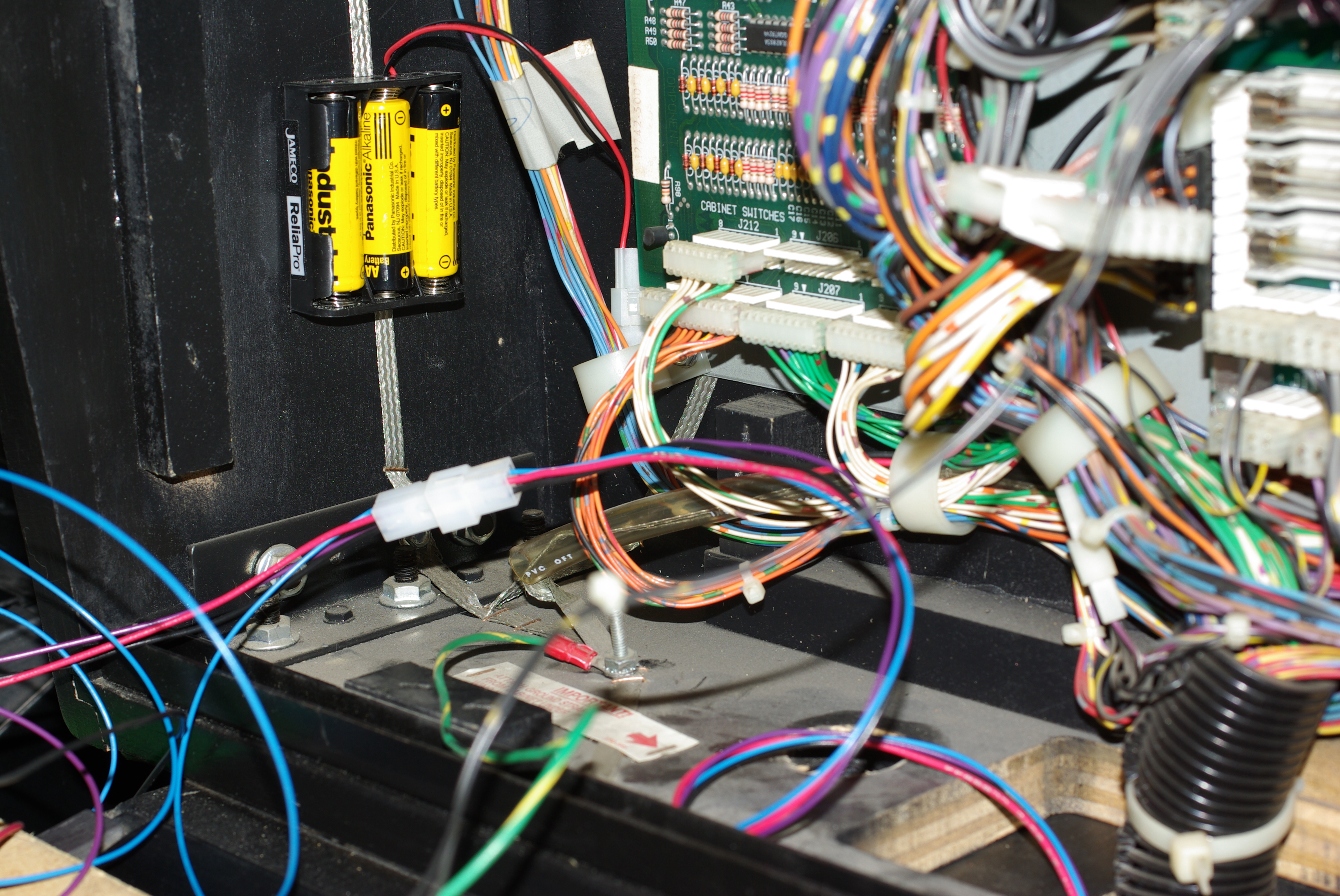
Feed the wiring through the cable clip at the lower left of the backbox. you want the connection to be about 3 inches up from the clip. |
| Run the black wire with the ring terminal down through the cable clip, and secure it to the ground stud. | The red, purple and blue wires go up to the backboard. |
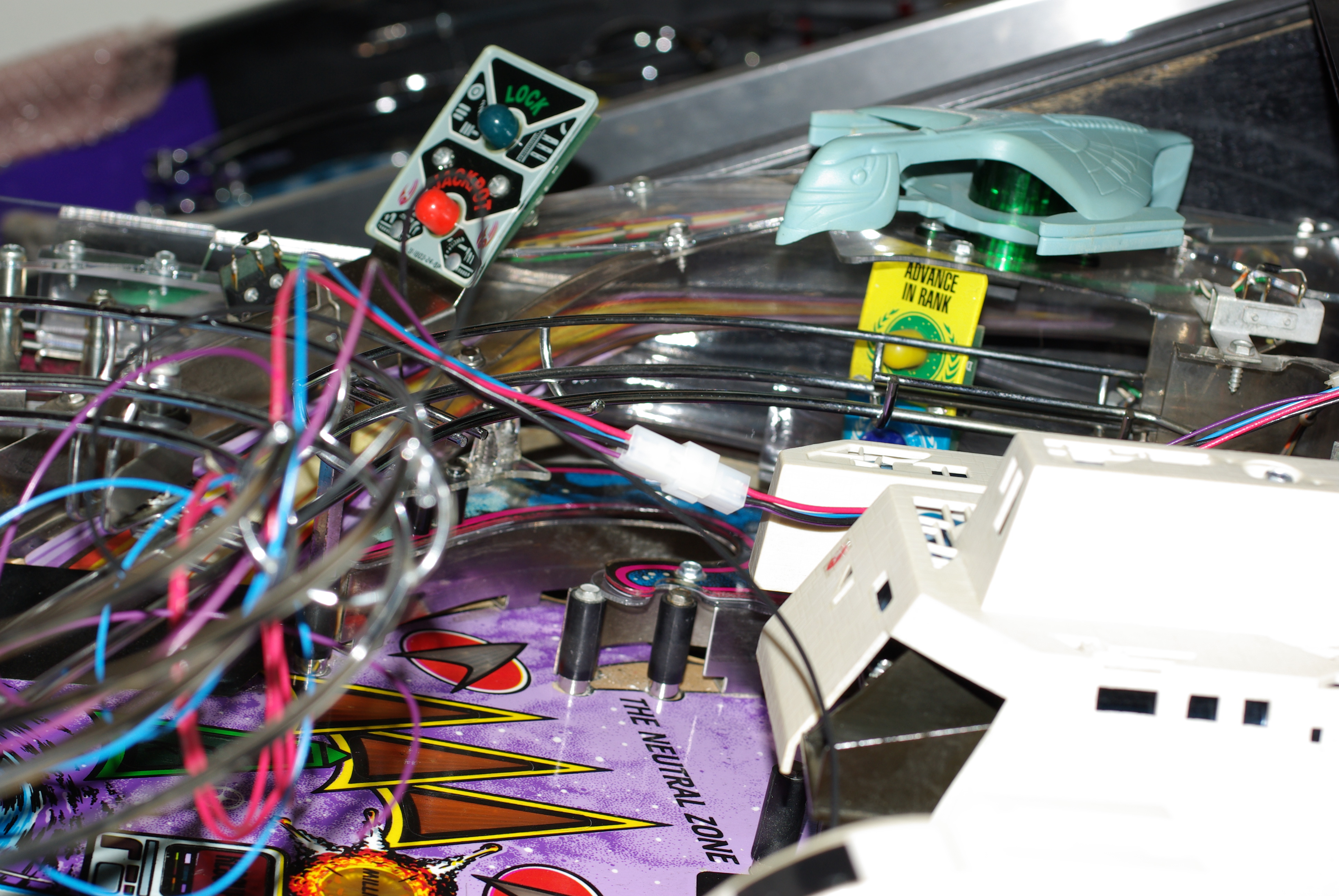
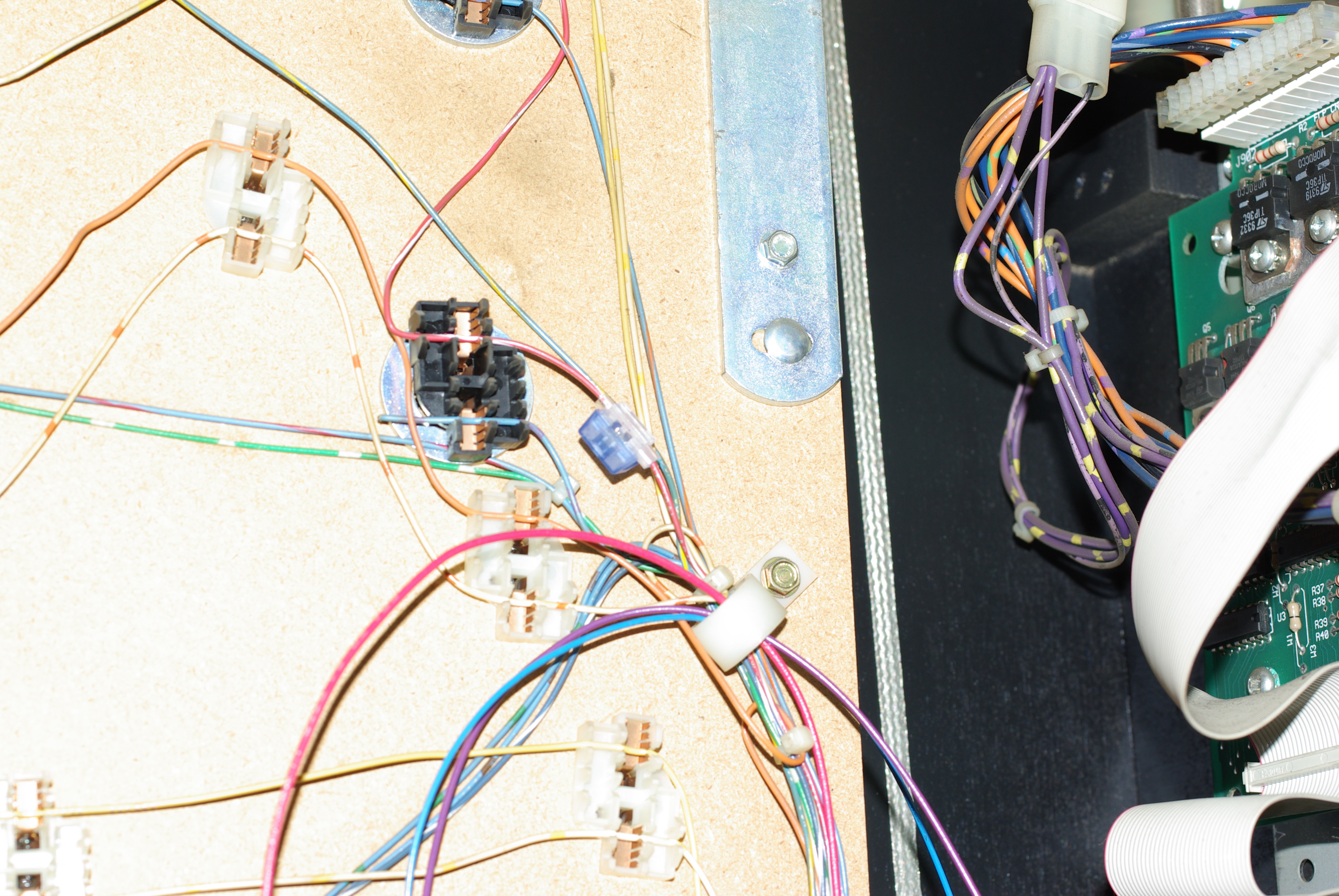 Place
a tap onto the red/white wire that daisy chains between the
flashers. Use the through side, not the dead end.
Make sure that it is properly inside the
connector body. Place
a tap onto the red/white wire that daisy chains between the
flashers. Use the through side, not the dead end.
Make sure that it is properly inside the
connector body. |
 Trim
the red harness wire to the right length, and push it home into the
connector. When everything is right, squeeze the tap shut with the
pliers. Remember, parallel pressure is essential. Trim
the red harness wire to the right length, and push it home into the
connector. When everything is right, squeeze the tap shut with the
pliers. Remember, parallel pressure is essential. |
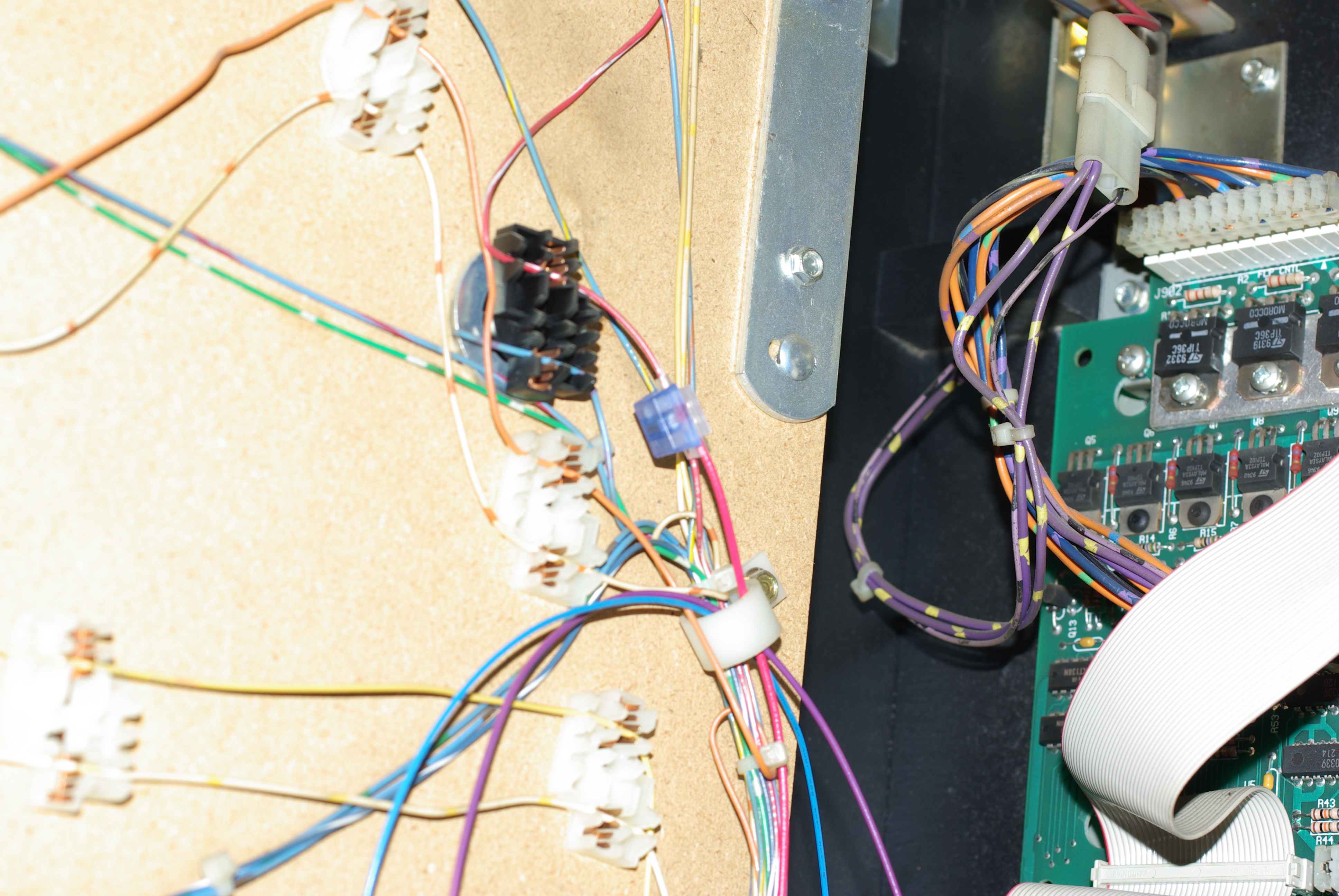
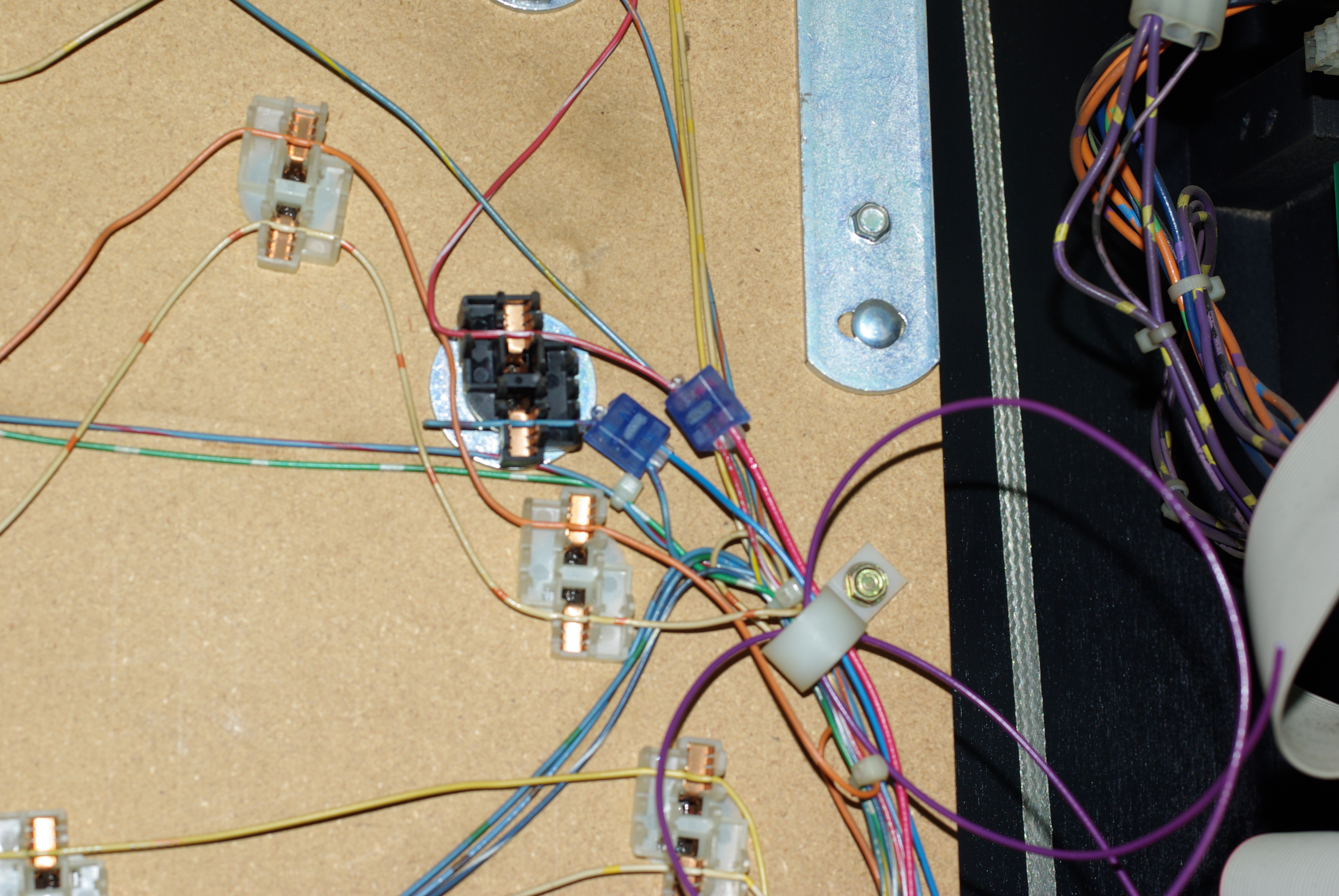 The
blue wire taps into the blue-violet flasher wire. it is the first
flasher (black connector) in the wiring chain. The
blue wire taps into the blue-violet flasher wire. it is the first
flasher (black connector) in the wiring chain. |
The purple wire is for later. One day, we may use it for an enhancement. Just curl it up for now. |
| Dress your wiring with cable ties. The new harness should go down into the cabinet through the slit grey tubing. | That's it. Hook up the connector, and your machine should run. |
| Troubleshooting:
Nothing will work if the coin door is open as the flasher power is disconnected by the safety switch in the door. Push this switch in to test. The red light on the board should be on indicating power. If it is out, check your flasher fuse. On power up, the board will flash its machine ID (3 or 4 for ST:TNG) and then its version number. The motor will not run. When the shields flash, the purple LED should flash and the motor should run. If it doesn't flash, check the backbox wiring.
|
If the purple light flashes and the motor doesn't run, check the
motor connection. Also, double check that the red wire in the backbox is connected to the red/white flasher power wire. If it is connected to a flasher signal, the board will appear to work correctly but the motor will not run. This is because the system is drawing power through a flasher bulb. You can test the motor by grounding the screw head that holds the transistor and heatsink down. Make sure that the motor is securely mounted. If it does not run, there is a good chance that it is that red/white connection in the backbox. |