I prefer the greater robustness of red LEDs for this mod. And Pam says that
the red LEDs look better in the game. Using the hold coil keeps all the wiring
inside the assembly. If I was inspired, I would rewire the power connector and
add a Molex disconnect. But I am not that inspired right now.
 First,
we have to drill the eyes out. I used a 0.116" drill. This is about
right for snug LEDs. 7/64" is the closest common size, which will be a
little bit tight, but the vinyl stretches easily. First,
we have to drill the eyes out. I used a 0.116" drill. This is about
right for snug LEDs. 7/64" is the closest common size, which will be a
little bit tight, but the vinyl stretches easily.
|
 Drill
in the middle of the eyeballs. Drill straight down, you want vertical
holes. Here you see the LEDs ready for bending; set them up with the
flats to the left. Get the drilling burrs out from the inside of the
head, they will be a nuisance otherwise.. Drill
in the middle of the eyeballs. Drill straight down, you want vertical
holes. Here you see the LEDs ready for bending; set them up with the
flats to the left. Get the drilling burrs out from the inside of the
head, they will be a nuisance otherwise.. |
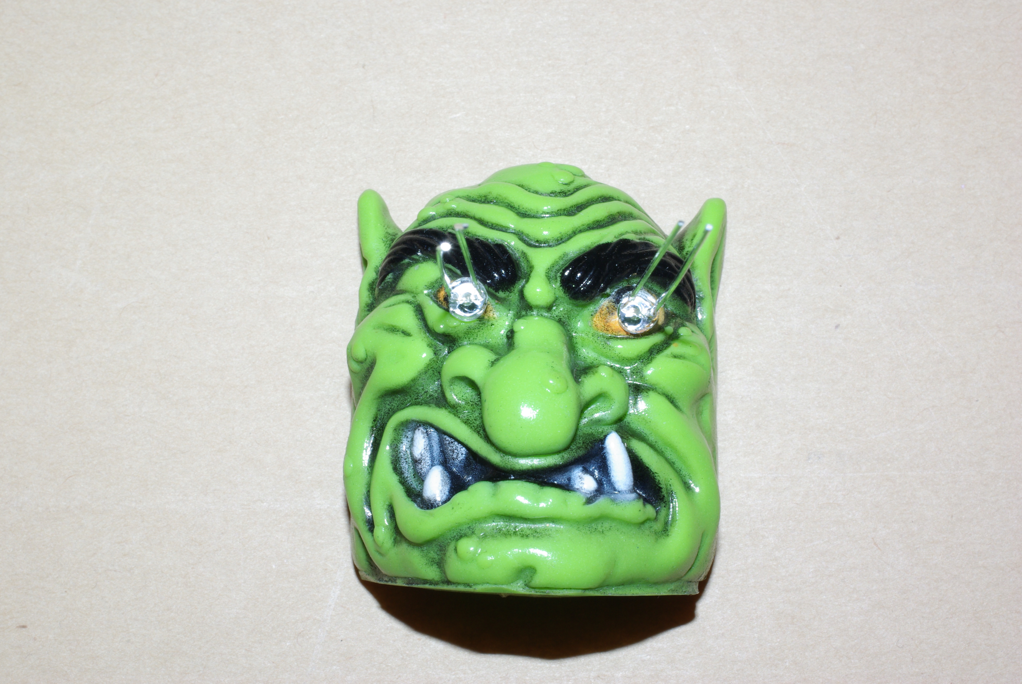
 Stick
the LEDs into the outside of the troll's face, with the flat sides /
short legs to the left. Stick
the LEDs into the outside of the troll's face, with the flat sides /
short legs to the left. |
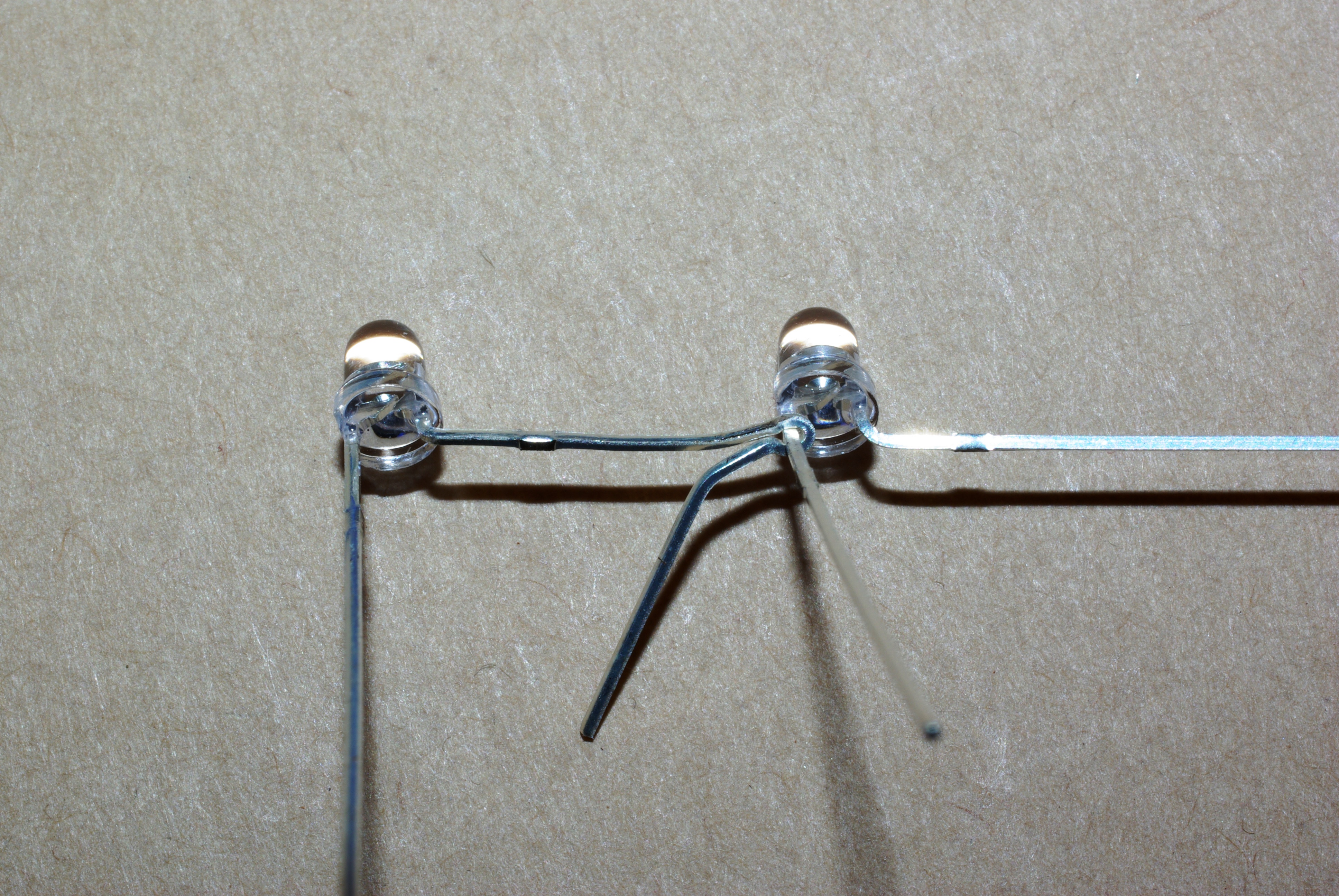
 Cut
the left leg of the right LED about 3/16" up. Bend the right leg of
the left led down, and create a little loop around the leg. trim the end
of the loop and the end of the leg. Cut
the left leg of the right LED about 3/16" up. Bend the right leg of
the left led down, and create a little loop around the leg. trim the end
of the loop and the end of the leg. |
 Remove
the LEDs from the face. Soldering iron scars will not look good on your
troll. Separate
the wires, and slip a piece of heatshrink over the long leg. Connect
them back together, tighten the loop, and solder. Be quick: these little
LEDs don't like overheating. Remove
the LEDs from the face. Soldering iron scars will not look good on your
troll. Separate
the wires, and slip a piece of heatshrink over the long leg. Connect
them back together, tighten the loop, and solder. Be quick: these little
LEDs don't like overheating. |
 Attach wires to the outside legs and put heatshrink on them.
I do this by tinning the wire and the leg, and then soldering them
together along the length of the wire. Cut the black wire that goes to the flat side of the LED a
little short so that you will recognize it- this is the negative lead. Attach wires to the outside legs and put heatshrink on them.
I do this by tinning the wire and the leg, and then soldering them
together along the length of the wire. Cut the black wire that goes to the flat side of the LED a
little short so that you will recognize it- this is the negative lead. |
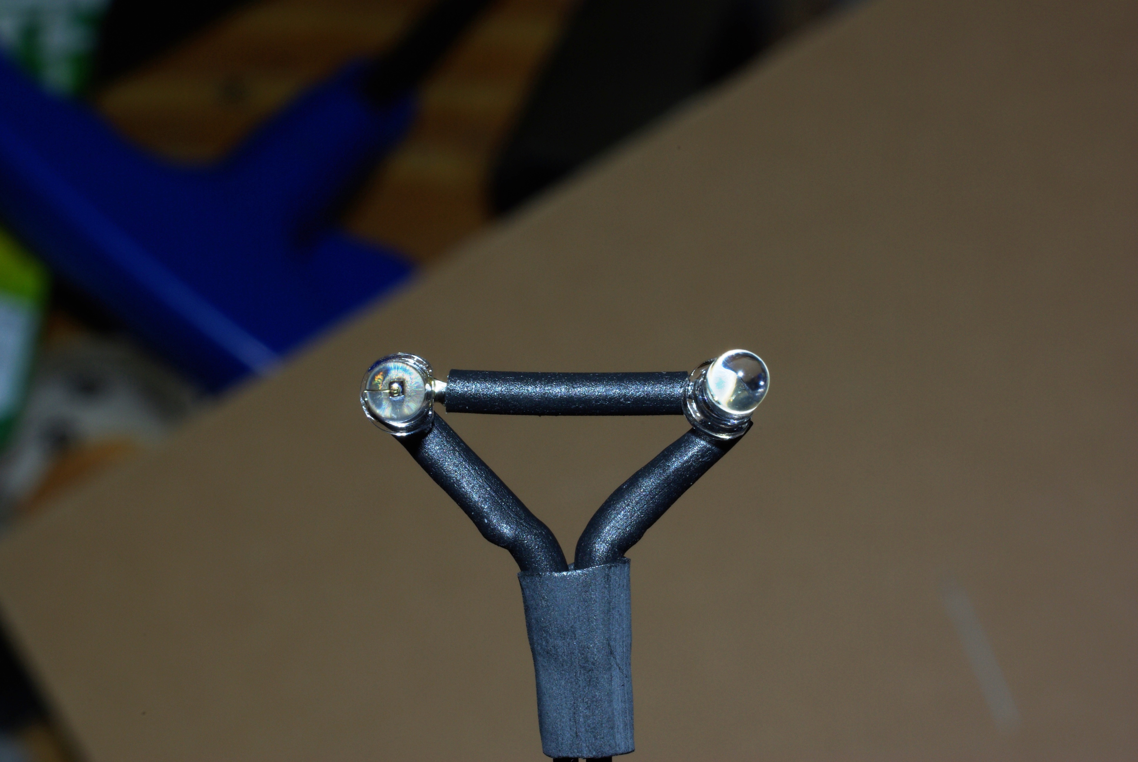
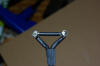 Put
one last piece of heatshrink over the wires, and make a triangle.
Tighten it all down with some hot air. Put
one last piece of heatshrink over the wires, and make a triangle.
Tighten it all down with some hot air. |
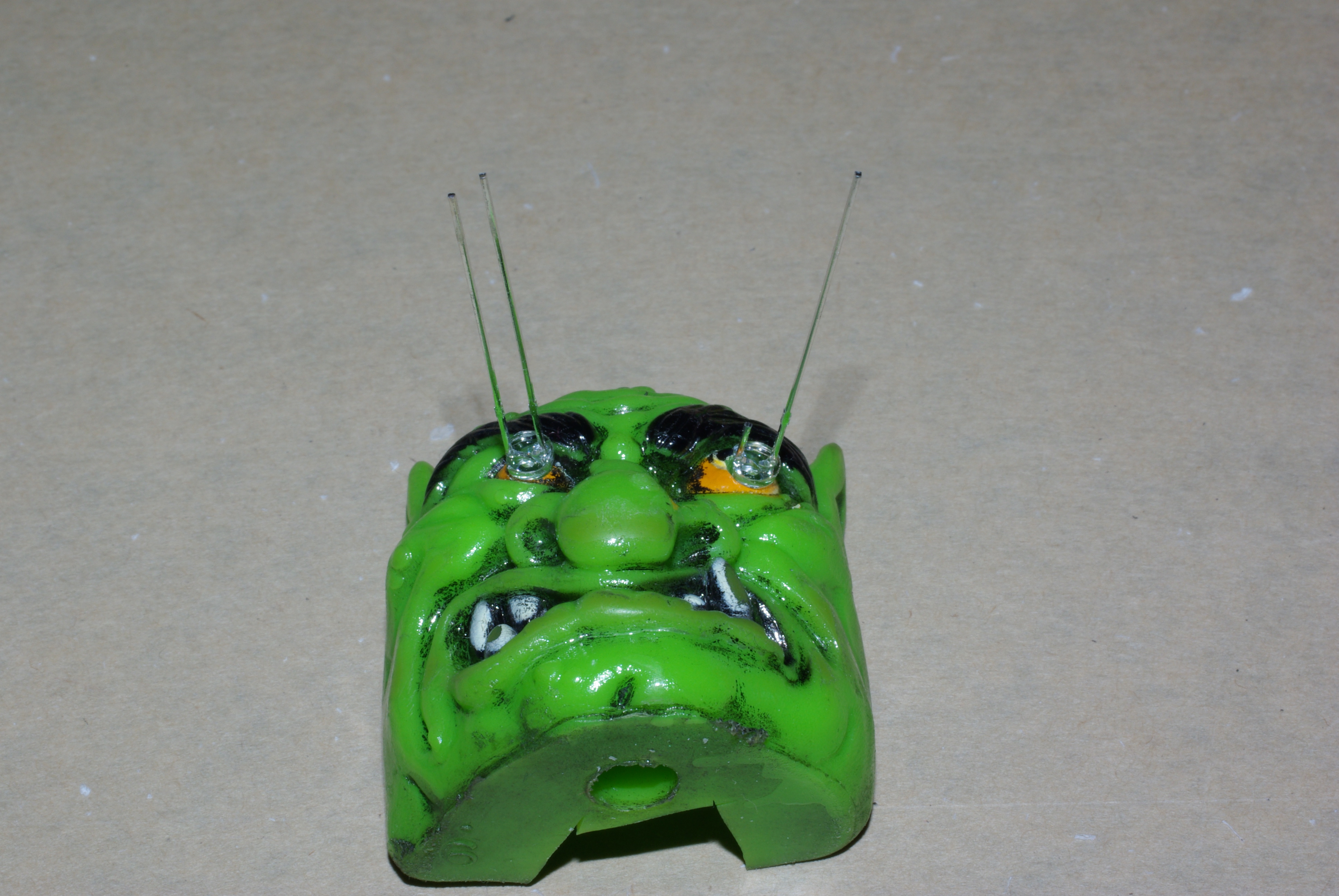
 Finally,
work the LEDs into the eyes from behind. By assembling them to the face
of the troll, you set the spacing right, but you still may need to bend them a
bit to get them in. Push them deep into the hoes using a screwdriver as
a lever. Pull the wires through the hole in the
bottom (you may have to open it up with a screwdriver). Push the wires
towards the front of the head. Finally,
work the LEDs into the eyes from behind. By assembling them to the face
of the troll, you set the spacing right, but you still may need to bend them a
bit to get them in. Push them deep into the hoes using a screwdriver as
a lever. Pull the wires through the hole in the
bottom (you may have to open it up with a screwdriver). Push the wires
towards the front of the head. |
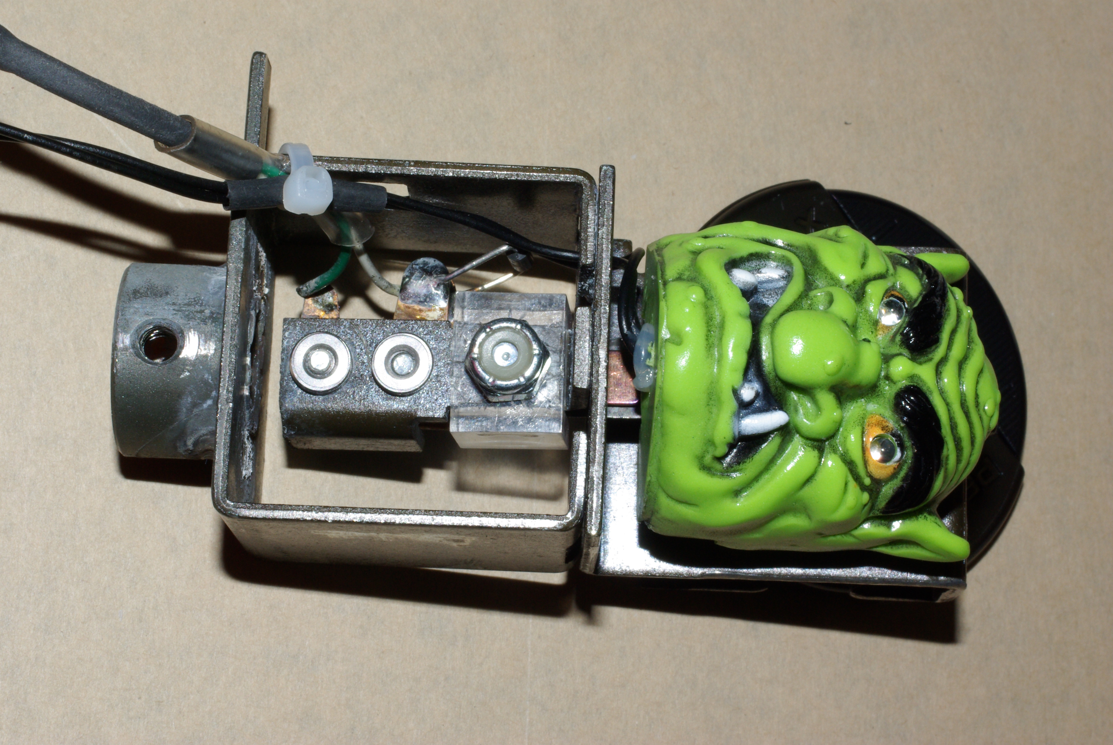
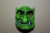
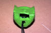
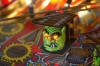
 Here's
the finished head. I filled the lower half of mine with silicone to hold
the LEDs and wiring in place, it is
going to be taking some action. I also put a blob of silicone in the
exit hole. Test your wiring by hooking the wires up to a
9V battery and the 510 ohm resistor. The long wire is positive. Here's
the finished head. I filled the lower half of mine with silicone to hold
the LEDs and wiring in place, it is
going to be taking some action. I also put a blob of silicone in the
exit hole. Test your wiring by hooking the wires up to a
9V battery and the 510 ohm resistor. The long wire is positive. |
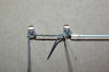
 Now
you can re-install the head. Run the new wires underneath the chin, away
from the switch blades, and along with the switch wiring. Put a piece of
heatshrink on the wire where it touches the carriage, and tighten it and
the switch wire down with a tie-wrap Now
you can re-install the head. Run the new wires underneath the chin, away
from the switch blades, and along with the switch wiring. Put a piece of
heatshrink on the wire where it touches the carriage, and tighten it and
the switch wire down with a tie-wrap |
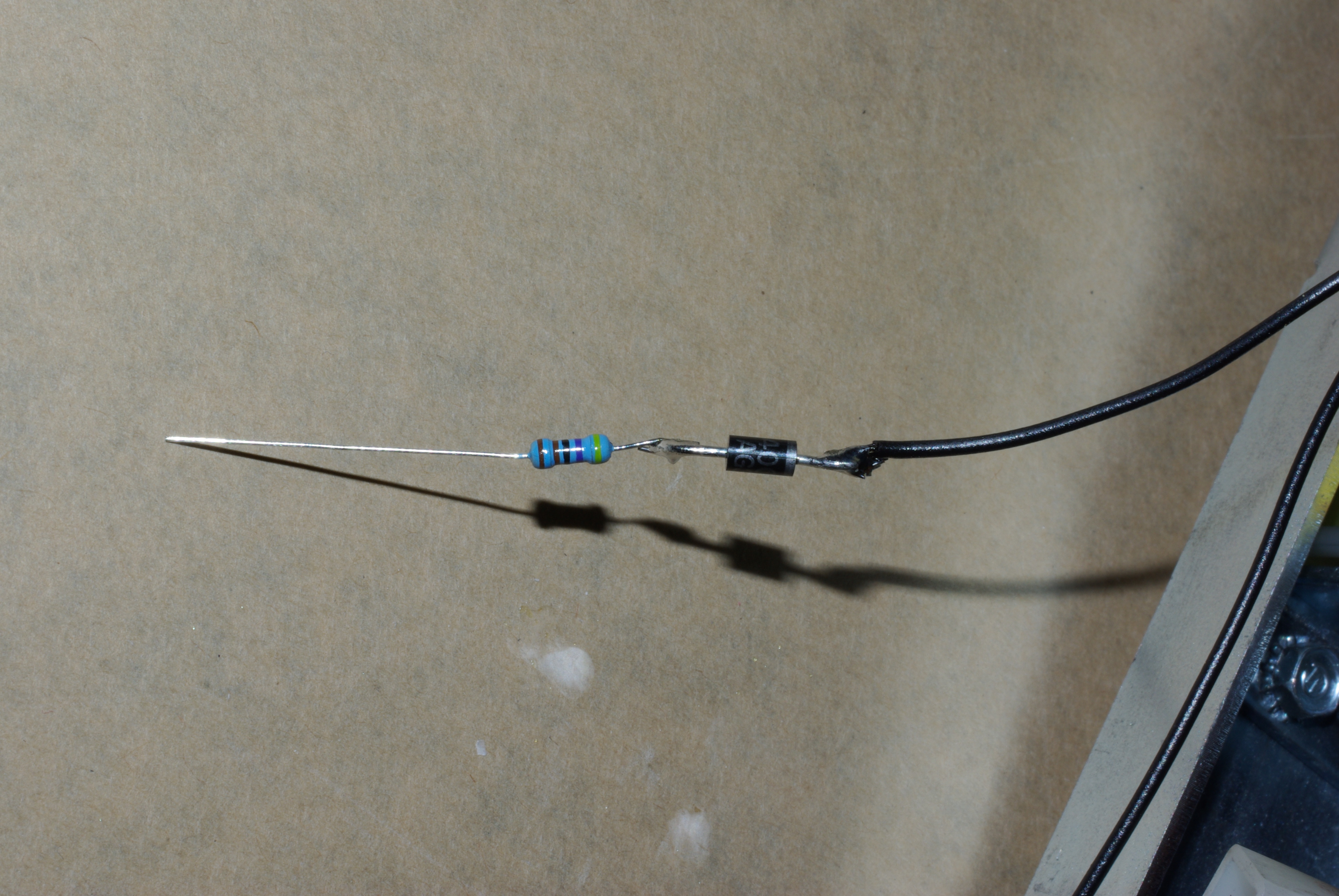
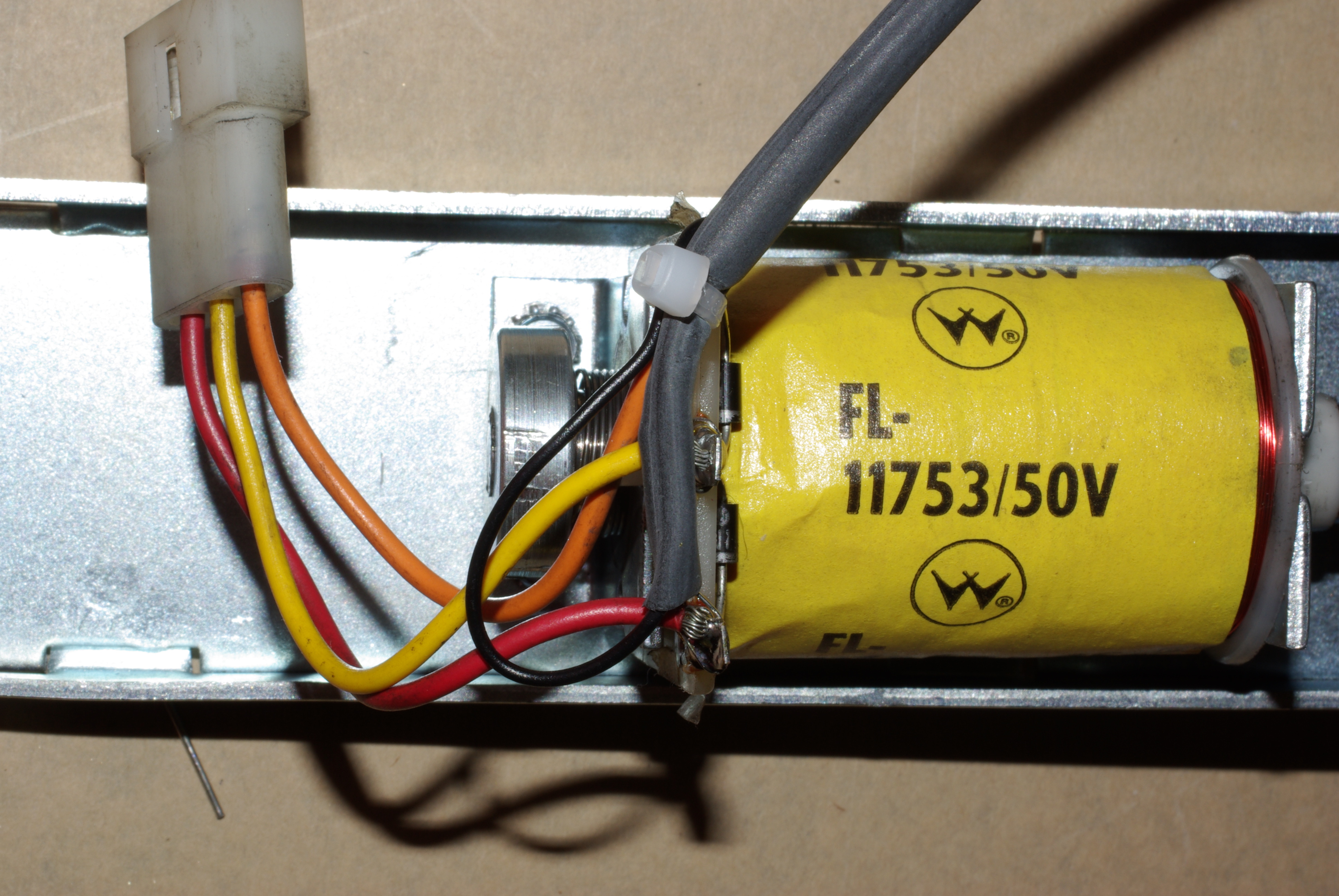
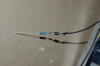 Next,
the wiring. Trim both wires to be about 5" longer than the run to the
solenoid. Keep track of the positive wire. positive wire Then, we
need a 1N4007 and a 3k6 resistor in the positive lead, wired in the
order shown. Your resistor may be a different color (our current
inventory has a brown body, and the test resistor is blue). Make little links out of
the wire and solder the parts together, we want tight joints. Next,
the wiring. Trim both wires to be about 5" longer than the run to the
solenoid. Keep track of the positive wire. positive wire Then, we
need a 1N4007 and a 3k6 resistor in the positive lead, wired in the
order shown. Your resistor may be a different color (our current
inventory has a brown body, and the test resistor is blue). Make little links out of
the wire and solder the parts together, we want tight joints.
|
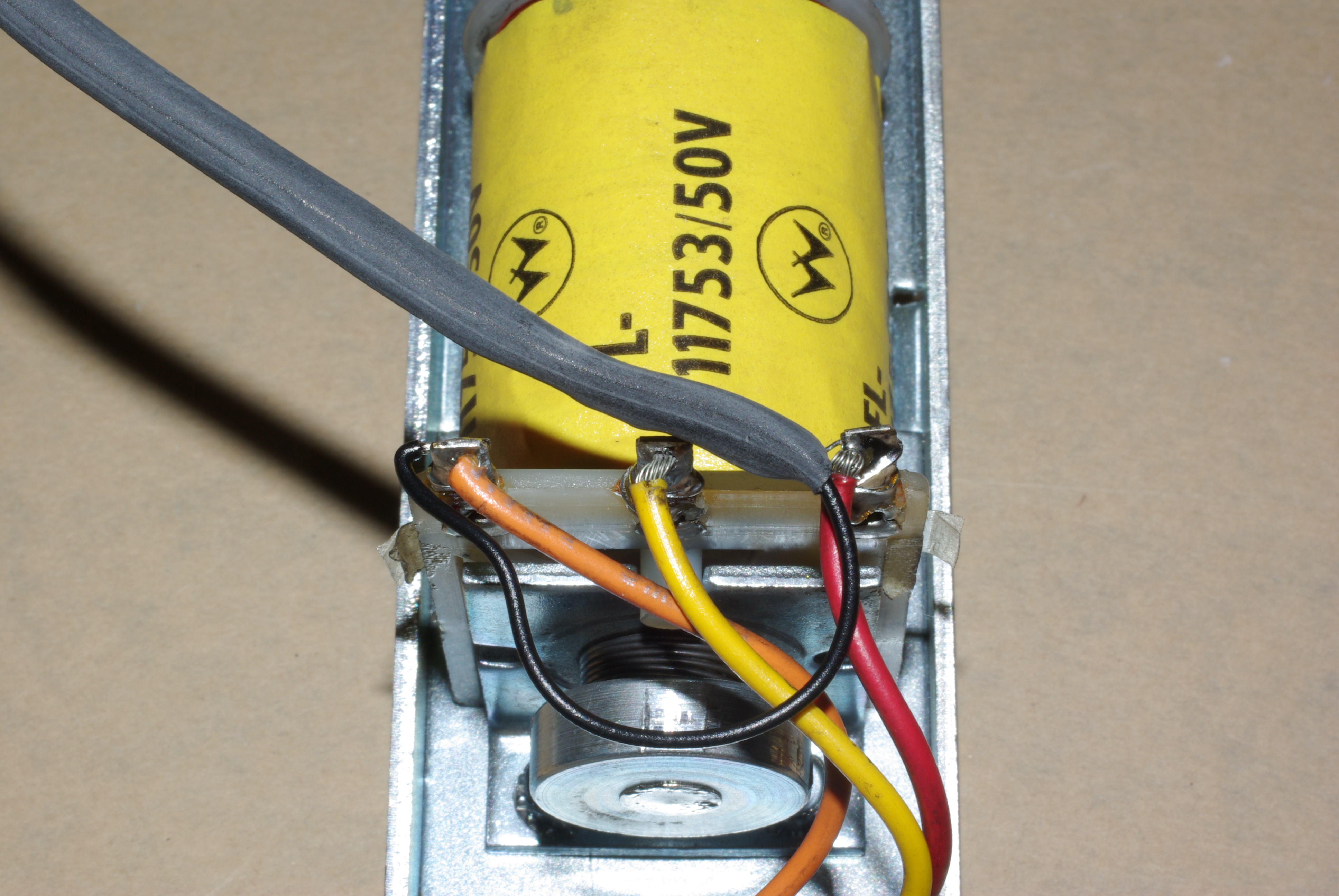
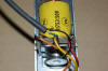 Slip
about 3" of 3/16 heatshrink over the wire and resistor assembly and
solder the resistor end to the red (right hand end) wire on the flipper
coil. Slip
about 3" of 3/16 heatshrink over the wire and resistor assembly and
solder the resistor end to the red (right hand end) wire on the flipper
coil. |
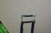
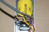 Pull
the heatshrink tight to the terminal lug, heat it up and lock it down. Pull
the heatshrink tight to the terminal lug, heat it up and lock it down. |
 Tidy
it all up with a tie-wrap. You should have a nice loop that readily
accommodates the carriage motion. Tidy
it all up with a tie-wrap. You should have a nice loop that readily
accommodates the carriage motion. |
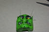
 Put
the troll in the machine and test it out - if you removed the flap, don't
replace it until
you have it all working. Then, don't forget to connect up the troll
target switch and the troll up switch. Put
the troll in the machine and test it out - if you removed the flap, don't
replace it until
you have it all working. Then, don't forget to connect up the troll
target switch and the troll up switch. |
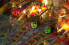 One
down, one to go! One
down, one to go! |
| |
|
| |
|
| |
|
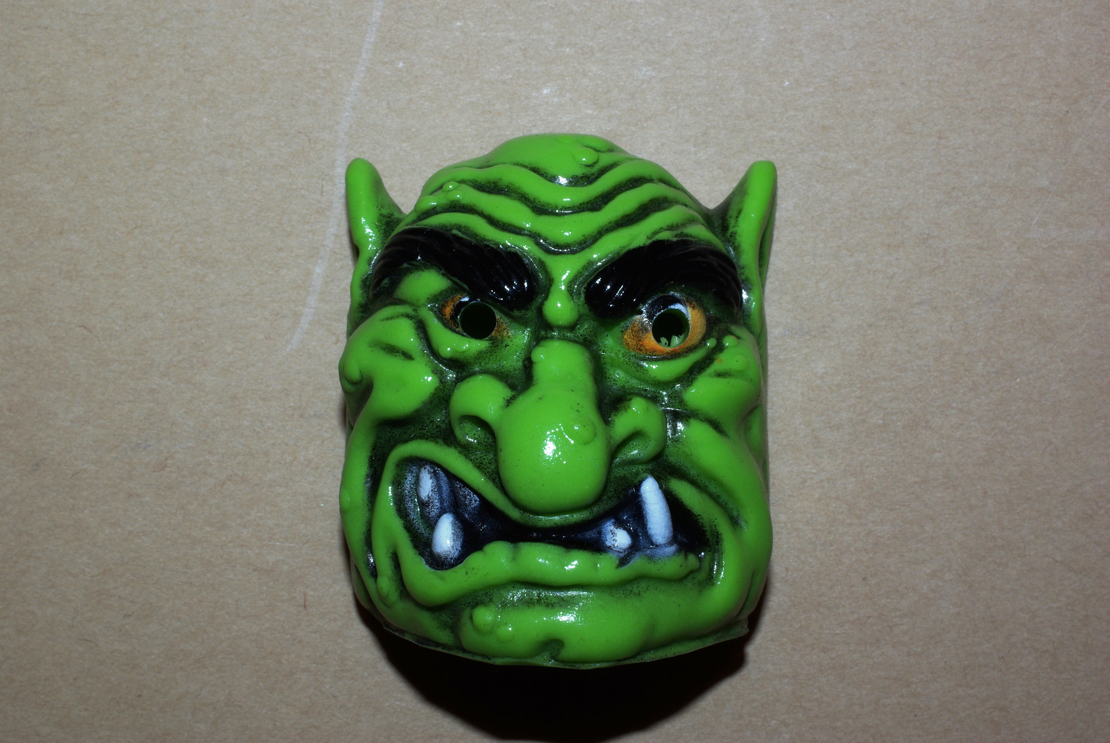
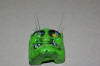
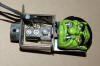
 So
I decided to put LEDs in my troll eyes. The first step is getting the LEDs into
the eyes themselves. I chose not to add any other circuitry in the head; the
head gets beaten about, so the less joints the better. My initial plan is to run
off of the troll hold coil. That's going to mean about 70V, so we'll be
using a 4k7 resistor to limit the current, and a diode to protect the LEDs
against any unforeseen happenings.
So
I decided to put LEDs in my troll eyes. The first step is getting the LEDs into
the eyes themselves. I chose not to add any other circuitry in the head; the
head gets beaten about, so the less joints the better. My initial plan is to run
off of the troll hold coil. That's going to mean about 70V, so we'll be
using a 4k7 resistor to limit the current, and a diode to protect the LEDs
against any unforeseen happenings.