
Opto Board
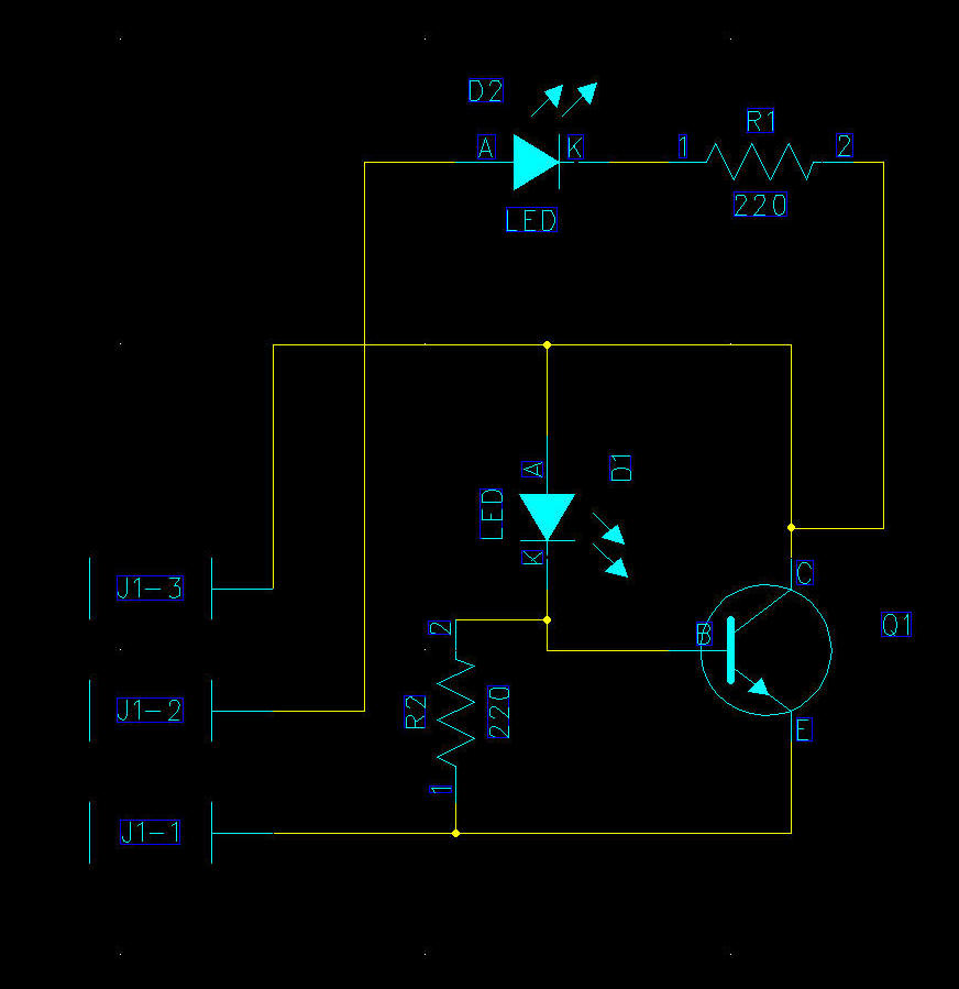
Here's the schematic for the new opto board. It has four functions:
High-current opto detector for direct connection to the switch matrix
Opto emitter tester - an LED shows the presence of infrared light, needs a 9V
battery
Regular opto emitter
12V opto emitter
The schematic is on the left, the layout on the right. Populate one side for the emitter, the other side for the receiver. The new board will take a 3-pin connector; I have also beefed up the pads for direct wiring.
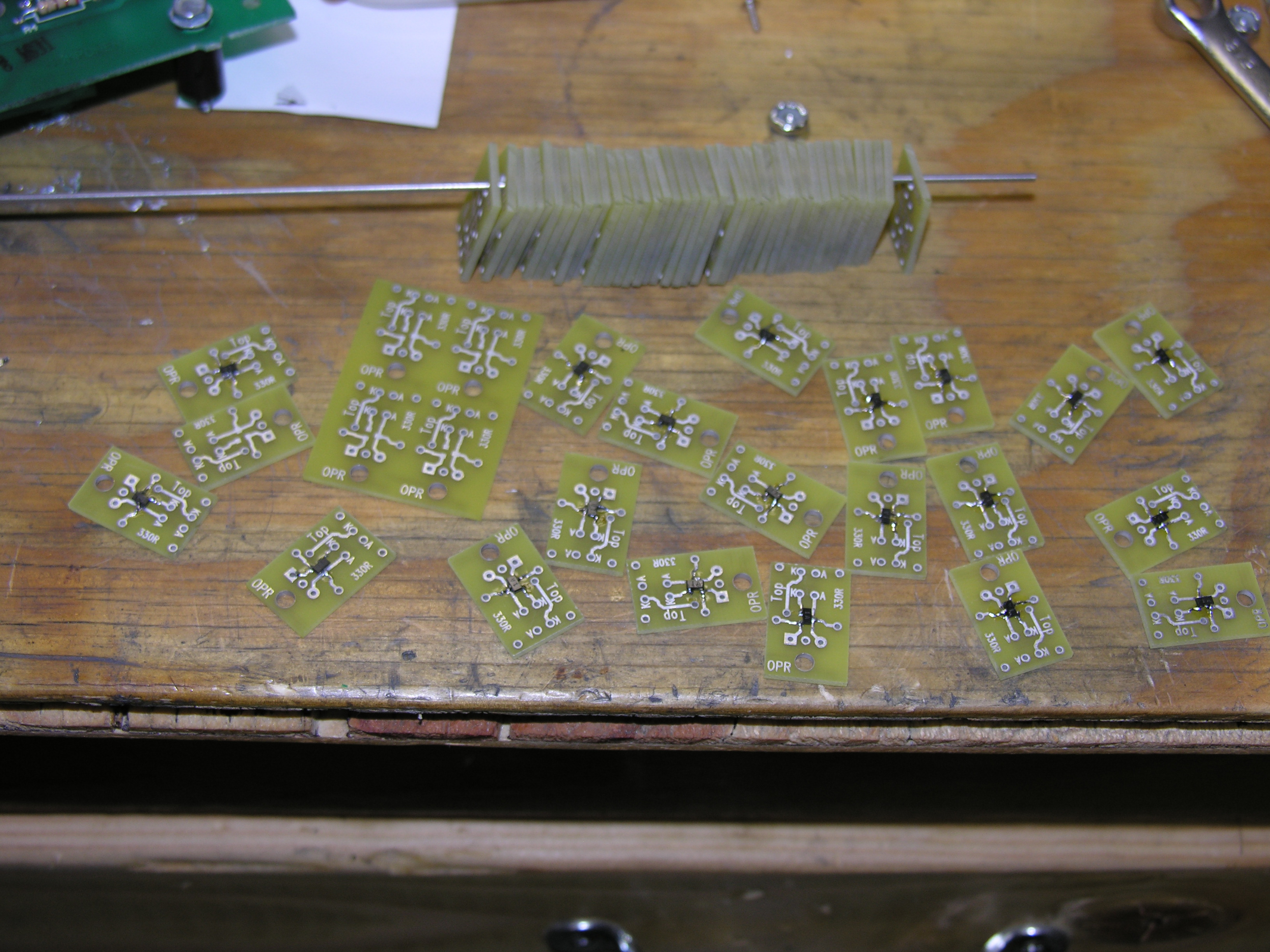 here
are the opto boards. The ones on the pole are blanks, sawn from sets of
four. that's a lot of sawing as the set has extra material on each side.
The board manufacturer centered the board for me. Oh well. here
are the opto boards. The ones on the pole are blanks, sawn from sets of
four. that's a lot of sawing as the set has extra material on each side.
The board manufacturer centered the board for me. Oh well.
The ones on the table have the SMT transistors installed, ready to be receivers or detector. |
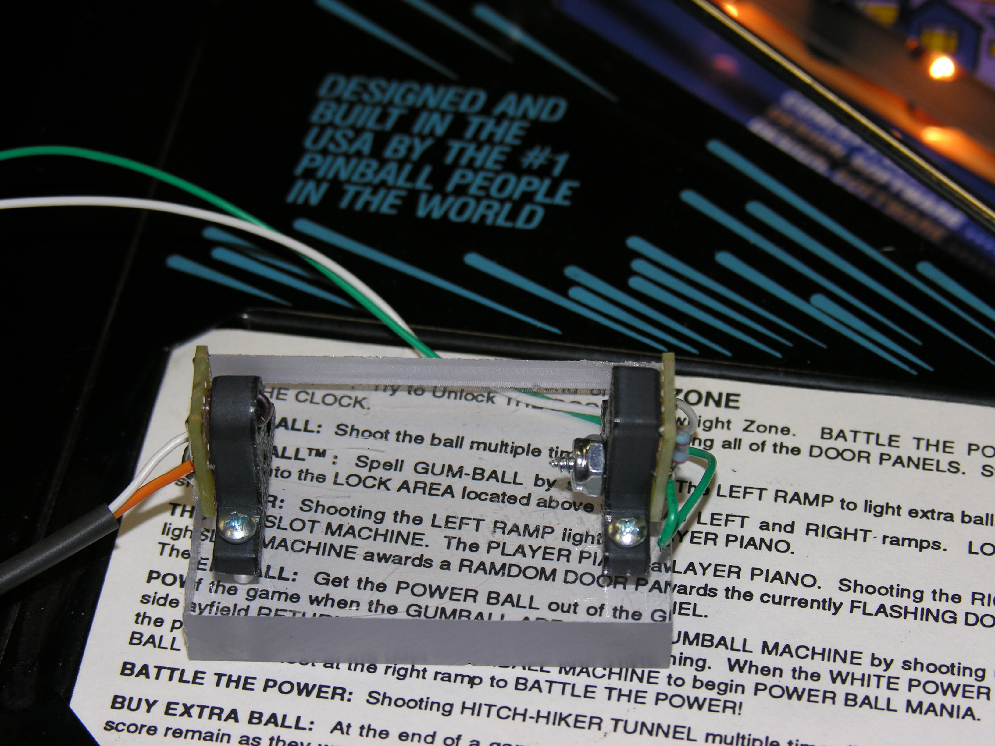 Here's
the opto and transmitter pair, connected on long leads to the machine.
They work perfectly, although I had to add a diode to the receiver. The
range is about 6 inches for an LED. A regular 44 bulb triggers it at
about 3 inches. Ordinary room lighting has no effect. This is the level
that I wanted. Here's
the opto and transmitter pair, connected on long leads to the machine.
They work perfectly, although I had to add a diode to the receiver. The
range is about 6 inches for an LED. A regular 44 bulb triggers it at
about 3 inches. Ordinary room lighting has no effect. This is the level
that I wanted. |
The newest version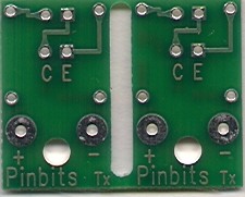 |