The auxiliary driver board, under the playfield near the left lower flipper
mechanism, uses only five of its eight slots. However, the transistor that we
need will most likely not be in your machine, so we are going to have to add it.
We also have to add the wiring for the third magnet coil.
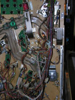 Let's
start with the magnet wiring. Here's a picture of the rear of the upper
right quadrant of the playfield, which is the lower right quadrant when
the playfield is up and viewed from behind, like here. Let's
start with the magnet wiring. Here's a picture of the rear of the upper
right quadrant of the playfield, which is the lower right quadrant when
the playfield is up and viewed from behind, like here. |
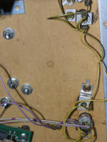 And
here's where the magnet will go. Note the three dimples at the lower end
of the open space in the picture. We'll be back here later, with some
tools... And
here's where the magnet will go. Note the three dimples at the lower end
of the open space in the picture. We'll be back here later, with some
tools... |
| The magnet cable harness is a 2-pin connector with two
long 18GA black wires attached. |
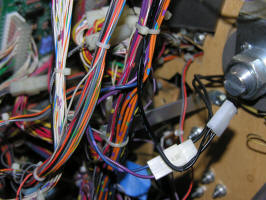 Start
by holding the connector and wiring alongside the wiring for the
existing magnet. I tucked mine through the existing wire tie. Start
by holding the connector and wiring alongside the wiring for the
existing magnet. I tucked mine through the existing wire tie. |
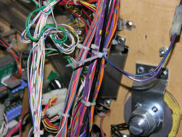 Run
the wiring up the harness; our goal is the driver board, up in the top
left of the machine. Add cable ties next to the factory ties, and try to
keep the wires in roughly the same position as they run up the harness.
We don't want this to look like some kind of climbing weed. Run
the wiring up the harness; our goal is the driver board, up in the top
left of the machine. Add cable ties next to the factory ties, and try to
keep the wires in roughly the same position as they run up the harness.
We don't want this to look like some kind of climbing weed. |
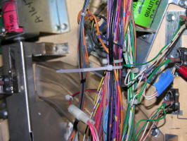 Here
I messed up. the black wires should go under the flipper wires. I'll fix
that when I rewire the flippers. Here
I messed up. the black wires should go under the flipper wires. I'll fix
that when I rewire the flippers. |
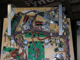 You
can see the route by following the unclipped cable ties. You
can see the route by following the unclipped cable ties. |
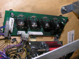 When
you have the wires run, disconnect the driver board, remove it, and add
the transistor and other parts. See below for adding the transistor. When
you have the wires run, disconnect the driver board, remove it, and add
the transistor and other parts. See below for adding the transistor. |
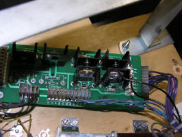 That
was quick! Here's the board with the new transistor added. You can see
the new wires hanging over the board. That
was quick! Here's the board with the new transistor added. You can see
the new wires hanging over the board. |
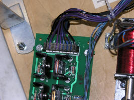 Finish
up by pushing the new wires into the open sockets at each end of the
connector (+50V and SOL2). This is best done with the playfield in the
lower service position (brackets resting on the front of the cabinet).
If you look carefully, you'll see that I messed up on SOL2. My wire is
not all the way in. I have fixed this. Finish
up by pushing the new wires into the open sockets at each end of the
connector (+50V and SOL2). This is best done with the playfield in the
lower service position (brackets resting on the front of the cabinet).
If you look carefully, you'll see that I messed up on SOL2. My wire is
not all the way in. I have fixed this. |
| |
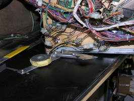
DON'T TRY TO LOWER THE PLAYFIELD!!!
Here's the new magnet, connected and in a good location for test. Go
into solenoid test, and test Solenoid 22 ("Not Used"). It will buzz as
the test routines fire it.
DON'T TRY TO LOWER THE PLAYFIELD!!! |
|
Adding the Extra Transistor |
|
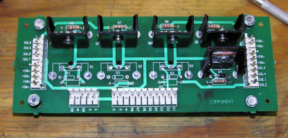 Here's
the board, after a bath, on the bench. We are going to add Q3, D3 and
R3. Here's
the board, after a bath, on the bench. We are going to add Q3, D3 and
R3. |
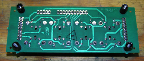
First, we have to empty the holes of solder. To do this, we need
solder ucker and a soldering iron. We could also use braid, but I prefer
the sucker. |
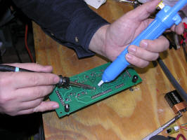 Cock
the solder sucker, then apply the iron to the hole that you wish to
clean. Cock
the solder sucker, then apply the iron to the hole that you wish to
clean. |
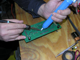 Put
the sucker over the hole and the iron. Then, release the plunger. The
solder will be sucked out of the hole. Put
the sucker over the hole and the iron. Then, release the plunger. The
solder will be sucked out of the hole. |
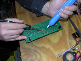 It
is effective on larger holes. The smaller resistor holes might take two
tries. I clean out the heatsink holes, even though we will probably not
use them. It
is effective on larger holes. The smaller resistor holes might take two
tries. I clean out the heatsink holes, even though we will probably not
use them. |
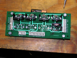 Here's
the board with the holes cleaned out. Here's
the board with the holes cleaned out. |
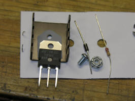 Here
are the parts that we will add. You can see the transistor, thermal pad
and heatsink on the left, and then the diode and the resistor. The screw
and nut fasten the transistor to the heatsink with the pad between them.
. Here
are the parts that we will add. You can see the transistor, thermal pad
and heatsink on the left, and then the diode and the resistor. The screw
and nut fasten the transistor to the heatsink with the pad between them.
. |
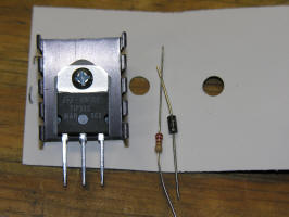 Here's
the transistor assembled. Here's
the transistor assembled. |
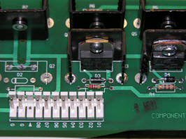 Put
all the parts into the holes. Make sure that the band on the diode is at
the left hand end, as shown on the board. You can put the resistor in as
you like. Put
all the parts into the holes. Make sure that the band on the diode is at
the left hand end, as shown on the board. You can put the resistor in as
you like. |
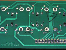 Bend
the leads outward at an angle while holding the parts cloes to the
board. This will make your life much easier. Bend
the leads outward at an angle while holding the parts cloes to the
board. This will make your life much easier. |
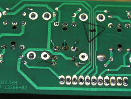 Now
you can solder the parts. Now
you can solder the parts. |
Finally, clip the leads close to the board and clean the flux off
with a bit of naptha. Re-install the board in the machine. This part is
done. |